Table of Contents
Advertisement
Quick Links
Advertisement
Table of Contents

Related Manuals for Major tech MT2005


Summary of Contents for Major tech MT2005
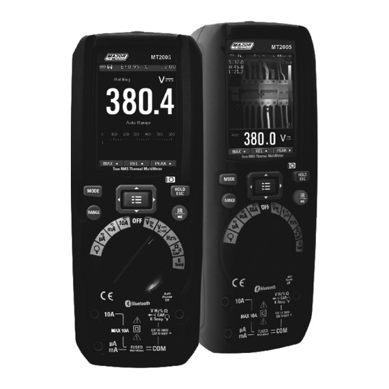
- Page 1 MT2005 True-RMS Thermal MultiMeter...
-
Page 3: Table Of Contents
Content Page Introduction ........................ 4 Safety 2.1. Safety Information ....................4 2.2. Safety Instructions ....................6 Description and reference guide Front and back description ..................7 Understanding the Push Buttons ................8 Understanding the Display ..................9 Understanding the Rotary Switch ................1 0 DMM Measurement &... -
Page 4: Introduction
1. INTRODUCTION Professional True RMS Industrial Digital Multimeter with built-in Thermal Imager, and TFT color LCD display, providing fast A/D converting sampling time, high accuracy. It is a fast and easy solution to find and solve problems with production equipment, providing Bluetooth technology BLE. It is a safe instrument with double molded plastic housing and has a IP65 waterproof rating. - Page 5 This symbol advises the user that the terminal(s) so marked must not be connected to a circuit point at which the voltage with respect to earth ground exceeds (in this case) 1000 VAC or VDC. This WARNING symbol indicates a potentially hazardous situation, which if not avoided, could result in death or WARNING serious injury.
-
Page 6: Safety Instructions
2.2 Safety Instructions This meter has been designed for safe use, but must be operated with caution. The rules listed below must be carefully followed for safe operation. NEVER apply voltage or current to the meter that exceeds the specified maximum: Input Protection Limits Function Maximum Input... -
Page 7: Description And Reference Guide
3. Description and reference guide 3.1 Front and back descriptions NCV detector area LCD Display Navigation/Menu buttons MODE button RANGE button Rotary function switch Positive(+) Probe input jack for A (Current). Positive(+) Probe input jack for mA (Current). COM(-) Probe input jack 10. -
Page 8: Understanding The Push Buttons
3.2 Understanding the Push Buttons The 9 push buttons on the front of the Meter activate features that augment the function selected using the rotary switch, navigate Cursor buttons Select an item in the menu, adjust display contrast, scroll through Ÿ... -
Page 9: Understanding The Display
3.3. Understanding the Display Measurement on LCD Dispaly Indication of battery charge level Indication of measuring result Indication of Automatic/Manual mode Analogue bargraph Indications associated with function keys Indication of the system's time Indication of measuring unit SD card Temperature measuring result 10. -
Page 10: Understanding The Rotary Switch
3.4. Understanding the Rotary Switch Select a primary measurement function by positioning the rotary switch to one of the icons around its perimeter. For each function, the Meter presents a standard display for that function (range, measurement units, and modifiers). Button choices made in one function do not carry over into another function. -
Page 11: Dmm Measurement & Setup
4. DMM Measurement and Setup 4.1. DC Voltage Measurements CAUTION: Do not measure DC voltages if a motor on the circuit is being switched ON or OFF. Large voltage surges may occur that can damage the meter. Set the function switch to the VDC position. -
Page 12: Ac Voltage Measurements
4.3. AC Voltage Measurements WARNING: Risk of Electrocution. The probe tips may not be long enough to contact the live parts inside some 240V outlets for appliances because the contacts are recessed deep in the outlets. As a result, the reading may show 0 volts when the outlet actually has voltage on it. -
Page 13: Resistance Measurements
4.5. Resistance Measurements To avoid electric shock, disconnect power to the unit under test and discharge all capacitors before taking any resistance measurements. Remove the batteries and unplug the line cords. Set the function switch to the position. Insert the black test lead banana plug into the negative COM jack. -
Page 14: Diode Test
4.7. Diode Test Set the function switch to the Ω CAP position. Insert the black test lead banana plug into the negative COM jack. Insert the red test lead banana plug into the positive V jack. Press the MODE key to switch the Diode functions. -
Page 15: Temperature Measurements
4.9. Temperature Measurements Set the function switch to the TEMP(°C or °F) position. Insert the Temperature Probe into the input jacks, making sure to observe the correct polarity. Read the temperature in the display. Press the MODE key to switch the Unit (C°... -
Page 16: Dc Current Measurements
4.11. DC Current Measurements Insert the black test lead banana plug into the negative COM jack. For current measurements up to 6000µA DC, set the function switch to the µA position and insert the red test lead banana plug into the µA/mA jack. For current measurements up to 600mA DC, set the function switch to the mA position and insert the red test lead... -
Page 17: Ac Current Measurements
4.12. AC Current Measurements CAUTION: Do not make 10A current measurements for longer than 30 seconds. Exceeding 30 seconds may cause damage to the meter and/or the test leads. Insert the black test lead banana plug into the negative COM jack. For current measurements up to 6000µA AC, set the function switch to the µA position and... -
Page 18: Ac+Dc Current Measurements
4.13. AC+DC Current Measurements CAUTION: Do not make 10A current measurements for longer than 30 seconds. Exceeding 30 seconds may cause damage to the meter and/or the test leads. Insert the black test lead banana plug into the negative COM jack. For current measurements up to 6000µA AC+DC, set the function switch to the µA position... -
Page 19: Using Range
4.14. Using RANGE Press the RANGE key to activate the manual mode and to disable the Auto range function. The message Manual Range appears on the upper left part of the display instead of Auto Range. In manual mode, press the RANGE key to change the measuring range: the relevant decimal point will change its position. -
Page 20: Capturing Minimum And Maximum Values
4.16. Capturing Minimum and Maximum Values The MIN/MAX Record mode captures minimum, and maximum input values. When the input goes below the recorded MINIMUM value or above the recorded MAXIMUM value, the Meter beeps and records the new value. This mode is for capturing intermittent readings, recording MINIMUM and MAXIMUM readings unattended, or recording readings while... -
Page 21: Capturing Peak Values
4.18. Capturing Peak Values To activate the PEAK mode, press the ► button. If the Meter is already in the PEAK function, press the ► button to deactivate PEAK mode. 4.19. Non-Contact AC Voltage Detector (100 to 1000V AC) WARNING: Risk of Electrocution. Before use, always test the Voltage Detector on a known live circuit to verify proper operation. -
Page 22: Thermal Imager & Dmm Operation
5. Thermal imager and DMM operation 5.1. Thermal imager basics In the Thermal imaging and DMM mode. The user can measure a targeted surface's temperature and can use the Multimeter at the same time, the measured result will display under the thermal image. Press the red IR button to open the Thermal Imager. -
Page 23: Using The Thermal Imager
10. Current scene of the Thermal image frame 11. Range icon of the meter 12. Max button 13. REL button 14. PEAK button 15. DMM measurement is shown below the thermal image. 16. Unit of the meter 17. Lowest reading measured in the current frame 18. - Page 24 The thermal imager's FOV (Field of view) is 21 by 21 degrees. FOV is the largest area that your imager can see at a set distance. 10. This table lists the horizontal FOV, vertical FOV and IFOV for the lense. FOVIFOV Focal Length Horizontal FOV...
-
Page 25: Capturing Min/Max Values On Ir+Dmm Mode
D:S (measure) [= 1/ IFOV (measure)] is the spot size needed to provide an accurate temperature measurement. Typically, D:S (measure) is 2 to 3 times smaller than D:S (theoretical), which means the temperature measurement area of the target needs to be 2 to 3 times larger than that determined by the calculated theoretical D:S. -
Page 26: Setting Menus
6. Settings Menus 6.1. Using Settings Menus Press MENU button to open the settings Press the UP/DOWN button to select menu item or change the value of current focus item. Press the RIGHT/MENU button to enter the submenu or set focus on the current selected item. -
Page 27: Measure
6.4. Measure Press the RIGHT/MENU button to enter the measure menu. There are two selections that are available: HOT POINT and COLD POINT. Press the RIGHT/MENU button to set selected item to ON or OFF. HOT POINT: This option enables the ●... -
Page 28: Setup
6.7. Setup Press the RIGHT/MENU button to enter common menu. There are Five options available: Beep, Bluetooth, Laser, Brightness and Auto Off. Beep: Use the RIGHT/MENU button ● to set beep on or off. Bluetooth: Use RIGHT/MENU ● button to set bluetooth power ON or OFF. -
Page 29: Time/Date
Turn on the bluetooth of the smartphone. Press the icon Thermview+ and enter into the home interface, then press the Connect Device icon on the Home interface, the bluetooth device name will appear. Touch the device name listed in Bluetooth devices list to connect to the device. -
Page 30: Memory
6.10. Memory Press RIGHT/MENU button to enter photo menu. There are two options that are available: PHOTO REVIEW and DELETE PHOTO. Photo Review: Press the RIGHT/MENU button to enter image browser function, and exit settings menus immediately. Delete Photo: Press the RIGHT/MENU button, a dialog box will be displayed as show below. -
Page 31: Factory Set
6.12. Factory Set Once Factory Set option has been selected, press the RIGHT/MENU button, the dialog box, as shown on the right will be displayed. Select the YES button, the system parameter will be reset. 7. Image Browser In the Image Browser mode, the User can browse the pictures in the memory card. -
Page 32: Technical Specifications
8. Technical Specifications 8.1. Technical characteristics Thermal imager Field of view (FOV) / Minimum focus distance 21° x 21°/ 0.5m Spatial resolution (IFOV) 4.53mrad IR resolution 80 x 80 pixels < 0.1°C @ +30°C (+86°F) / 100 mK Thermal sensitivity/NETD Image frequency 50Hz Focus mode... - Page 33 AC+ DC TRMS Voltage Protection against Range Resolution Accuracy Input impedance overcharge 6.000V 0.001V 60.00V 0.01V ±(2.4%reading + 1000V DC/AC RMS >10MΩ 20dgt) 600.0V 0.1V 1000V DC Current Protection against Range Resolution Accuracy overcharge 600.0uA 0.1uA ± (0.9%reading + 5digits) 6000uA Quick fuse 800mA/1000V 60.00mA 0.01 mA...
- Page 34 Resistance and Continuity test Protection against Range Accuracy Buzzer Resolution overcharge ± (0.5%reading + 10dgt) 600.0Ω 0.1Ω 6.000kΩ 0.001kΩ 60.00kΩ 0.01kΩ ±(0.5%reading + 5digits) 1000V DC/AC RMS >50Ω 600.0kΩ 0.1kΩ 6.000MΩ 0.001MΩ ± (2.5%reading + 10dgt) 60.00MΩ 0.01MΩ Frequency (electronic circuits) Protection against Range Accuracy...
- Page 35 Capacity Protection against Range Accuracy Resolution overcharge ± (1.5%reading + 20digits) 60.00nF 0.01nF ± (1.2%reading + 8digits) 600.0nF 0.1nF ± (1.5%reading + 8digits) 6.000uF 0.001uF 1000V DC/AC RMS ± (1.2%reading + 8digits) 60.00uF 0.01uF ± (1.5%reading + 8digits) 600.0uF 0.1uF ±...
-
Page 36: Environment
Reference standards ● IEC/EN61010-1 Safety: IEC/EN 61326-1 EMC: Double insulation Insulation: Pollution level: CAT IV 600V, CAT III 1000V Overvoltage category: 2000m (6562ft) Max operating altitude: General characteristics ● Mechanical characteristics Size (L x W x H): 175 x 85 x 55mm Weight (batteries included): 540g ●... -
Page 37: Optional Extra Mt740
8.3. OPTIONAL EXTRA (MT740) Technical Specifications Best Output Range Measurement Accuracy Function Voltage Range 30A AC ≤30.00A 100mV/A ± (3.0% + 5mV) AC Current 50~400Hz 300A AC 30.0A-300.0A 10mV/A ± (3.0% + 3mV) True RMS 3000A AC 300A-3000A 1mV/A ± (3.0% + 3mV) Note: Accuracy is given as ±(% of reading + counts of least significant digit) at ·... -
Page 38: General Specification
8.4. General Specifications Range Function Power indication: Green LED light Low Battery indication: Red LED light Operating Temperature: 5°C to 40°C (41°F to 104°F ) Storage Temperature: -20°C to 60°C (-4°C to 140°C ) Operating Humidity: Max 80% up to 31°C (87°F) decreasing linearly to 50% at 40°C (104°F) Storage Humidity: <80%... - Page 40 MAJOR TECH (PTY) LTD T9 Industrial Village, 7 Sam Green Road, Telephone: +27 11 872 5500 Tunney Ext. 9, Elandsfontein, Sales Facsimile: +27 11 822 2806 South Africa Admin Facsimile: +27 11 822 1411 P .O. Box 888, Isando 1600, E-mail: sales@major-tech.com...
Need help?
Do you have a question about the MT2005 and is the answer not in the manual?
Questions and answers