Table of Contents
Advertisement
Quick Links
Advertisement
Table of Contents

Related Manuals for Major tech MT22


Summary of Contents for Major tech MT22
- Page 1 INSTRUCTION MANUAL MT22 1000V AC/DC MULTIMETER...
-
Page 3: Table Of Contents
Contents Page no 1. Safety Information................4 2. Safety Symbols..................4 3. Controls and Jacks................5 4. Symbols and Annunciators..............6 5. Specifications..................6 5.1. DC Voltage (Auto Ranging)............7 5.2. AC Voltage (Auto Ranging except 200mV)........7 5.3. DC Current (Auto Ranging for uA and mA)........7 5.4. -
Page 4: Safety Information
1. SAFETY INFORMATION The following safety information must be observed to insure maximum personal safety during the operation at this meter: Ÿ Do not use the meter if the meter or test leads look damaged, or if you suspect that the meter is not operating properly. Ÿ... -
Page 5: Controls And Jacks
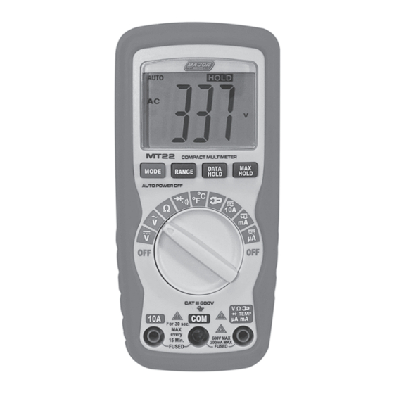
Input Limits Function Maximum Input V DC or V AC CAT II-1000V DC /AC CAT III-600V DC /AC mA DC/AC 200mA DC/AC A DC/AC 10A DC/AC (30 seconds max every 15 minutes) Resistance, Diode test, 500V DC/AC Continuity Temperature 3. CONTROLS AND JACKS 1 - 2000 count Liquid Crystal 6 - Mode push button: selection Display with symbolic signs... -
Page 6: Symbols And Annunciators
4. SYMBOLS AND ANNUNCIATORS Continuity Low Battery Diode DATA HOLD Data Hold AUTO AutoRanging Alternating Current or Voltage Direct Current or Voltage 5. SPECIFICATIONS Range Function The instrument complies with: EN61010-1 Insulation: Class 2, Double insulation Overvoltage category: CAT III 600V, CAT II 1000V Display: 2000 counts LCD display with function indication... -
Page 7: Dc Voltage (Auto Ranging)
5.1. DC Voltage (Auto Ranging) Range Resolution Accuracy 200.0mV 0.1mV ±0.5% of rdg ±2 dgts 2.000V 20.00V 10mV ±1.2% of rdg ±2 dgts 200.0V 100mV 600V(CAT III) ±1.5% of rdg ±2 dgts 1000V(CAT II) ±1.5% of rdg ±4 dgts Input Impedance: 10MΩ. Maximum Input: 600V DC/AC RMS.(CATIII) Maximum Input: 1000V DC/AC RMS.(CATII) 5.2. -
Page 8: Ac Current (Auto Ranging For Ua And Ma)
5.4. AC Current (Auto-ranging for uA and mA) Range Resolution Accuracy 200.0uA 0.1uA ±1.5% of rdg ±5 dgts 2000uA 20.00mA 10uA ±1.8% of rdg ±5 dgts 200.0mA 100uA 10mA ±3.0% of rdg ±7 dgts Overload Protection: 0.2A / 250V and 10A / 250V Fuse. Frequency Range: 50 to 60 Hz Maximum Input:... -
Page 9: Resistance (Auto Ranging)
5.7. Resistance (Auto-ranging) Range Resolution Accuracy 200.0Ω 0.1Ω ±1.2% of rdg ±4 dgts 2.000kΩ 1Ω ±1.0% of rdg ±2 dgts 20.00kΩ 10Ω 200.0kΩ 100Ω ±1.2% of rdg ±2 dgts 2.000MΩ 1kΩ 20.00MΩ 10kΩ ±2.0% of rdg ±3 dgts Input Protection: 500V DC or 500V AC RMS. 5.8. -
Page 10: Mode Button
NOTE: On some low AC and DC voltage ranges, with the test leads not connected to a device, the display may show a random, changing reading. This is normal and is caused by the high-input sensitivity. The reading will stabilize and give a proper measurement when connected to a circuit. 6.1. -
Page 11: Ac Voltage Measurements
6.6. AC VOLTAGE MEASUREMENTS WARNING: Risk of Electrocution. The probe tips may not be long enough to contact the live parts inside some 240V outlets for appliances because the contacts are recessed deep in the outlets. As a result, the reading may show 0 volts when the outlet actually has voltage on it. -
Page 12: Ac Current Measurements
6.8. AC CURRENT MEASUREMENTS WARNING: To avoid electric shock, do not measure AC current on any circuit whose voltage exceeds 250V AC. CAUTION: Do not make current measurements on the 10A scale for longer than 30 seconds. Exceeding 30 seconds may cause damage to the meter and/or the test leads. -
Page 13: Resistance Measurements
6.10. RESISTANCE MEASUREMENTS WARNING: To avoid electric shock, disconnect power to the unit under test and discharge all capacitors before taking any resistance measurements. Remove the batteries and unplug the line cords. Set the function switch to the Ω position. Insert the black test lead banana plug into the negative (COM) jack and the red test lead banana plug into the positive Ω... -
Page 14: Temperature Measurements
6.13. TEMPERATURE MEASUREMENTS WARNING: To avoid electric shock, disconnect both test probes from any source of voltage before making a temperature measurement. If you wish to measure temperature in °F, set the function switch to the °F range. If you wish to measure temperature in °C, set the function switch to the °C range. -
Page 15: Replacing The Fuses
Insert the battery into battery holder, observing the correct polarity. Put the battery cover back in place. Secure with the two screws. WARNING: To avoid electric shock, do not operate the meter until the battery cover is in place and fastened securely. NOTE: If your meter does not work properly, check the fuses and battery to make sure that they are still good and that they are properly inserted. - Page 16 MAJOR TECH (PTY) LTD South Africa Australia www.major-tech.com www.majortech.com.au sales@major-tech.com info@majortech.com.au...
Need help?
Do you have a question about the MT22 and is the answer not in the manual?
Questions and answers