Table of Contents
Advertisement
Quick Links
Advertisement
Table of Contents

Related Manuals for Major tech MT915


Summary of Contents for Major tech MT915
- Page 1 INSTRUCTION MANUAL MT915 2-IN-1 CABLE IDENTIFIER & DIGITAL MULTIMETER...
-
Page 3: Table Of Contents
Contents Page no 1. Applications General................4 2. Front Panel Description..............4 2.1. Transmitter Description.............4 2.2. Receiver Description..............4 2.3. Digital Multimeter Description.............4 3. Specifications & Technical Data............5 3.1. DMM..................5 3.2. Transmitter................6 3.3. Receiver...................6 4. Measuring Procedure.................6 4.1. Transmitter & Receiver Operation..........6 4.2. Beep Alarm Test................7 4.3. -
Page 4: Applications General
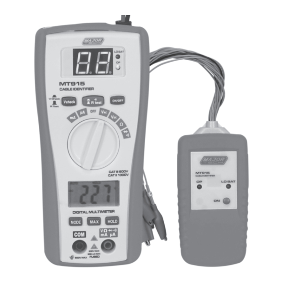
1. APPLICATIONS GENERAL The MT915 is a transmitter/receiver device which enables one person to instantly match up ends of individual cores at either end of a multi-core cable. With the remote kit it can tester cables installed far away either on wall plate or patch panel. -
Page 5: Specifications & Technical Data
3. SPECIFICATIONS & TECHNICAL DATA 3.1. DMM Function Range Accuracy DC Voltage 200mV, ±(0.5% rdg + 3d) 2.000V, 20.00V, ±(1.0% rdg + 3d) 200.0V, 600V ±(1.0% rdg + 3d) AC Voltage 2.000V, 20.00V ±(1.0% rdg + 5d) 50-60Hz 200.0V, 600V ±(1.5% rdg + 10d) DC Current 200.0μA, 2000μA... -
Page 6: Transmitter
3.2. TRANSMITTER Range Function Display Two red LED lamps Aligators 17 Croc clips-red*16,black*1 Cable resistance 30K Ohm max Power 9V battery Power current 1.8mA Operating temperature 0°C to 40°C (32°F to 104°F) Storage temperature –10°C to 50°C (14°F to 122°F) 3.2. -
Page 7: Beep Alarm Test
4.2. Beep alarm test 1. Press the “TEST” button in on the Cable Identifier. 2. Connect the 2 Croc Clips to both sides of a cable to check the continuity. If the cable is fine a beep sound will be heard. CAUTION: Beep if less than 100Ω. -
Page 8: Continuity Check
3. Touch the test probe tips across the circuit or part under test. It is best to disconnect one side of the part under test so the rest of the circuit will not interfere with the resistance reading. 4. Read the resistance in the display WARNING: To avoid electric shock, disconnect power to the unit under test and discharge all capacitors before taking any resistance measurements. -
Page 9: Replacing The Fuses
4.12. Replacing the Fuses 1. Disconnect the test leads from the meter. 2. Remove the protective rubber holster. 3. Remove the battery cover (two “B” screws) and thebattery. 4. Remove the four “A” screws securing the rear cover. 5. Lift the center circuit board straight up from the connectorsto gain access to the fuse holders. - Page 12 MAJOR TECH (PTY) LTD South Africa Australia www.major-tech.com www.majortech.com.au sales@major-tech.com info@majortech.com.au...
Need help?
Do you have a question about the MT915 and is the answer not in the manual?
Questions and answers