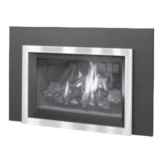
Enviro E30 Owner's Manual
Gas insert - log set w/ nova
Hide thumbs
Also See for E30:
- Owner's manual (39 pages) ,
- Installation manual (4 pages) ,
- Manual (8 pages)
Table of Contents
Advertisement
Quick Links
E3 0
G A S I N S E R T - LO G
S E T w /
N O V A
OW N E R 'S M A N U A L
WARNI NG:
I f the information in this manual is not follow ed exactly,
a fire or explosion may result causing property damage, personal
injury or loss of life. I nstallation and service must be performed by a
qualified installer, service agency or the gas supplier.
Report # 0268N023S
CERTI FI ED TO/ CERTI FI É AUX: ANSI Z21.88 / CSA2.33 VENTED GAS FI REPLACE HEATERS
50-2498
Version Française: www.enviro.com/fr.html
Advertisement
Table of Contents

Related Manuals for Enviro E30


Summary of Contents for Enviro E30
- Page 1 I nstallation and service must be performed by a qualified installer, service agency or the gas supplier. Report # 0268N023S CERTI FI ED TO/ CERTI FI É AUX: ANSI Z21.88 / CSA2.33 VENTED GAS FI REPLACE HEATERS 50-2498 Version Française: www.enviro.com/fr.html...
-
Page 2: Safety Precautions
Safety Precautions WARNI NG: FI RE OR EXPLOSI ON HAZARD Failure to follow safety warnings exactly could result in serious injury, death, or property damage. - Do not store or use gasoline or other flammable vapors and liquids in the vicinity of this or any other appliance. - WHAT TO DO I F YOU SMELL GAS •... - Page 3 TO TOUCH GLASS. • I f the E30 unit is pulled out of its installation, and the vent- A barrier designed to reduce the risk of burns from the air intake system is disconnected for any reason, ensure that...
-
Page 4: Table Of Contents
Table of Contents Safety Precautions......................2 Table of Contents......................4 Codes And Approvals.......................5 Specifications........................6 Rating Label Location...................6 Dimensions......................6 I nstall Depth......................6 E30 Options Dimensions..................7 Operating I nstructions....................8 Lighting and Turning Off Instructions..............8 Pilot Light......................9 Venturi Adjustment....................9 Normal Sounds During Operation.................9 Burner Lighting....................10 Blower Speed......................10 Maintenance And Service....................11... -
Page 5: Codes And Approvals
After the unit has gone through the first burn, turn the unit off, let the unit get cold then remove the glass door and clean it with a good gas fireplace glass cleaner, available at your local ENVIRO dealer. See “... -
Page 6: Specifications
16.27 19.85 16.70 2.52 3.26 1.45 17.79 Figure 1: E30 Exterior Dimensions. nstaLL epth The install depth will vary depending on what surround panel is used. Table 1 shows the required depth for each surround panel. Surround Panel Required Depth Contemporary 16”... -
Page 7: E30 Options Dimensions
Specifications e30 o ptions imensions 8 " 25" 8 " 8 " Figure 2: E30 Contemporary Surround with Base Shelf and Riser. Table 2: E30 Options Dimensions. Regular Surround Contemporary Surround Extruded Surround Height 25” (635mm) 25” (635mm) 25” (635mm) Width ”... -
Page 8: Operating Instructions
Operating Instructions For Your Safety, Read Safety Precautions And Lighting Instructions Before Operating WARNI NG: I F YOU DO NOT FOLLOW THESE I NSTRUCTI ONS EXACTLY A FI RE OR EXPLOSI ON MAY RESULT, CAUSI NG PROPERTY DAMAGE, PERSONAL I NJURY OR LOSS OF LI FE. ighting anD uRning nstRuctions... -
Page 9: Pilot Light
Operating Instructions iLot ight 1. Turn off the gas to the fireplace. I f not recently done, remove the glass and let the unit air out for at least five (5) minutes to clear out any gas. Turn on gas to the heater. Leak test all joints with Thermocouple Thermopile soapy water. -
Page 10: Burner Lighting
After the unit has gone through the first burn, turn the unit OFF, including the pilot, and let the unit completely cool. Then remove the door and clean the glass with a good gas fireplace glass cleaner, available at your local Enviro dealer. See aIntenanCe... -
Page 11: Maintenance And Service
Maintenance And Service Warning: Failure to position the parts in accordance with this manual, or failure to use only parts specifically approved with this appliance, may result in property damage or personal injury. At least once a year, run through the following procedures to ensure the system is clean and working properly. -
Page 12: Cleaning The Firebox
The glass must be purchased from an ENVIRO dealer. No substitute materials are allowed. Remove the door (see page 11). The replacement glass will come with a new gasket installed. Remove any silicone remnants from the door. -
Page 13: Fuel Conversion
Fuel Conversion TO BE INSTALLED BY A QUALIFIED SERVICE AGENCY ONLY Please read and understand these instructions before installing. WARNING: This conversion kit shall be installed by a qualified service agency in accordance w ith the manufacturer’s instructions and all applicable codes and requirements of the authority having jurisdiction. - Page 14 Confirm the inlet and manifold pressures are within the acceptable ranges as directed in section ntIal ntallatIon I f the E30 has been installed onneCtIon anD estIng at an altitude higher than 2000ft (610m) it is required to de-rate the unit accordingly:...
-
Page 15: Initial Installation
28” (711 mm) ” (470 mm) 20” (508 mm) 16” (406 mm) NOTE: Space must be provided for gas line on left side of unit for servicing purposes. The E30 can only be installed into masonary or zero-clearance fireplaces. ombustibLe uiLD... -
Page 16: Vent Ing
Initial Installation QUALIFIED INSTALLERS ONLY Build Out - Must be all non-combustible material Surround Panel Figure 18: Installation with a non-combustible build out. Figure 25.1: I nstallation w ith Non-Combustible Build Out enting WARNING: This appliance has been designed to draw room air for proper heat circulation from the sides and bottom of the unit, and out the top front. - Page 17 Check for any tears in the liner at this point. I MPORTANT: The screws that hold the vent collar plate in its approved position must be installed. I f the E30 unit is pulled out of its installation, and the vent air intake system is disconnected NOTE: for any reason, ensure that the vent-air intake pipes are re-sealed with high-temperature sealant and reconnected with three (3) sheet metal screws evenly spaced.
-
Page 18: Baffle Plate Adjustment
It must be completely sealed. *This installation is not tested and is not covered by the certification of this appliance. Please contact authorities having jurisdiction in your area for restrictions* Figure 20: Alternate Installation of E30 affLe Late... -
Page 19: I Nstalling The Unit
4. Check that the chimney clean outs fit properly. The flue damper must be fully blocked open or removed for installation of the E30; the smoke shelves, shields and baffles may be removed if attached by mechanical fasteners. - Page 20 Initial Installation QUALIFIED INSTALLERS ONLY 5. Stretch the Ø3” (76mm) flex vent liners to the length needed to ensure they can be easily connected to the vent terminals. 6. Install the flex pipe assembly up through the chimney, M&G I CC DirectVent ensure that the pipe slides through far enough to connect EXCELDirect...
-
Page 21: Zero Clearance Fireplace I Nstallation
Initial Installation QUALIFIED INSTALLERS ONLY 14. As you push the unit into its final position in the fireplace, if the vent collar plate was removed, reinstall it on the stove by pulling it into the brackets on top and reinstall the two Torx T-20 screws. -
Page 22: Electrical Requirements
Initial Installation QUALIFIED INSTALLERS ONLY LectRicaL equiRements The fan will not operate if the appliance is cold. Once the unit is lit and the fan is set to the desired level, the fan will automatically turn on upon reaching operating temperature. The fan will automatically turn off after the appliance has cooled down. -
Page 23: Gas Line Connection
½ psig (3.45 KPa) or the valve exceeds will be damaged. Figure 29: ⅜” NPT Male Pipe Nipple w ith Cover Removed. Table 7: Orifice and Pressure Information. E30 with Log Set Main Burner Natural Gas Propane Gas Orifice: #37 DMS #52 DMS Max. -
Page 24: Adjusting The Pilot Flame
Initial Installation QUALIFIED INSTALLERS ONLY TO TEST VALVE PRESSURES (INPUT RATES): The pressure taps are located on the front side of the valve (see Figure 30). 1. Remove valve control knobs, then remove control panel. 2. Using a long flat bladed screwdriver, turn set screw one (1) turn counter-clockwise to loosen. 3. -
Page 25: Secondary Installation
Additional Base Shelf Risers can be fastened together to increase the height in increments of 2⅛” (54 mm). This Base Shelf may be used in conjunction with the any of the E30 surround panel options, and it may also be used with the E30 Trimmable Surround. The Base Shelf and Riser are sold separately. -
Page 26: Optional 3 And 4 Sided Trimmable Panels
Modifying the Surround Panel: The E30 Trimmable Surround Panels are large rectangular panels that may be cut for use in cases that a non- standard fireplace opening (e.g. an arched opening) is to be filled. Optionally this surround can be left uncut and placed in front of the fireplace opening. -
Page 27: Surround Panel I Nstallation
The wiring harness for the burner switch has one (1) blue wire, one (1) grey wire and two (2) purple wires. The blue wire connects to the blue wire on the E30 unit, the grey wire connects to the grey wire on the E30 unit, and the purple wires are used to connect an optional thermostat. -
Page 28: Firebox Liner And Burner Tube Removal / I Nstallation
NOTE: The firebox liners are fragile and should be handled gently. Ensure the E30 is turned off and allow the unit to cool. 2. Remove the glass door as shown in the aIntenanCe anD erVICe lass emoVal WARNI NG: Do not touch or attempt to remove the glass if the fireplace is not completely cool. -
Page 29: Log Set And Ember Removal / I Nstallation
Secondary Installation & b et anD mbeR nstaLLation RaDitionaL iRch NOTE: The logs are fragile and should be handled gently. WARNING : Failure to position the parts in accordance with these diagrams or failure to use only parts specifically approved with this appliance may result in property damage or personal injury. - Page 30 Secondary Installation Figure 52: left top log Place the on the right, on top of the rear log and left mid log. Locate the bottom on the far left grate arm. Figure 53: right top I nstall the on top of rear log and right mid log.
- Page 31 : There are 2 locating Note notches on the bottom side. Bottom Notch = E30 Top Notch = E33...
- Page 32 Secondary Installation Figure 58: Finally, rest the eft and right front chunks on the log grate and burner as shown. DO NOT cover any burner ports TI P: While the glass is still removed, it is recommended that the gas line be purged by lighting the pilot.
-
Page 33: Trouble Shooting
Trouble Shooting Problem Possible Cause Solution The main burner The gas valve may not be on. • Check that the gas control knob is in the “ON” position. does not ignite Thermostat is not calling for • Adjust the thermostat several degrees above ambient temperature. when called for. -
Page 34: Parts List
E30 Control Panel Knobs (Set 2) 50-2355 E30/ E33 H-Burner Tube 50-3653 E30 Door Complete 50-2505 E30 Glass C/ W Gasket (21.75” X 13.575”) 50-2506 Dual Bulb Door Gasket (10ft) 50-634 E30 Valve Cover with Gasket 50-2503 E30 Fan Only... -
Page 35: Parts Diagram - Components
Parts Diagram - Components... -
Page 36: Warranty
Wa rra nty fo r Enviro Gas Pro duc ts Sherwood Industries Ltd. (“Sherwood”) hereby warrants, subject to the terms and Exclusions conditions herein set forth, this product against defects in material and workmanship An expanded list of exclusions is available at www.enviro.com/help/warranty.html during the specified warranty period starting from the date of original purchase at retail. -
Page 37: Installation Data Sheet
I NLET GAS PRESSURE:_________in WC PHONE:___________________________________ MAIN BURNER ORIFICE:__________# DMS PILOT ORIFICE #_________OR________in diam. I NSTALLER’S SI GNATURE: _________________________________________ MANUFACTURED BY: SHERWOOD I NDUSTRI ES LTD. 6782 OLDFI ELD RD. SAANI CHTON, BC, CANADA V8M 2A3 www.enviro.com Summer, 2021 C-15549...
Need help?
Do you have a question about the E30 and is the answer not in the manual?
Questions and answers