Table of Contents
Advertisement
Quick Links
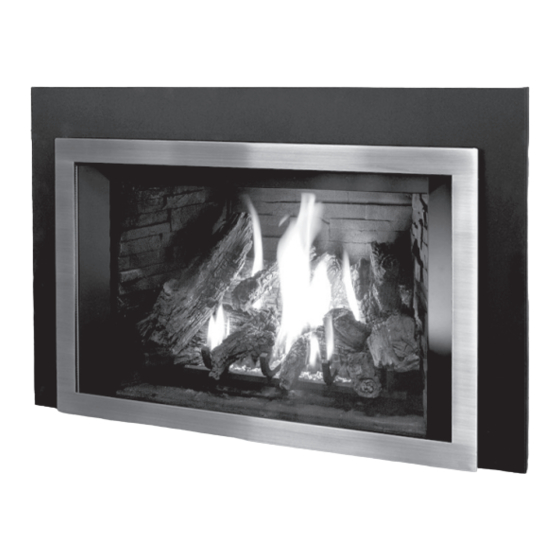
E33I / E33ID
G A S I N S E R T - L O G S E T w / I P I V a l v e
OWNER'S MANUAL
WARNING:
If the information in this manual is not followed exactly,
a fire or explosion may result causing property damage, personal
injury or loss of life. Installation and service must be performed by a
qualified installer, service agency or the gas supplier.
Report # 0268GN022S
CERTIFIED TO/ CERTIFIÉ AUX: ANSI Z21.88 / CSA2.33 VENTED GAS FIREPLACE HEATERS
50-2546
Version Française: www.enviro.com/fr.html
Advertisement
Table of Contents

Related Manuals for Enviro E33ID


Summary of Contents for Enviro E33ID
- Page 1 E33I / E33ID G A S I N S E R T - L O G S E T w / I P I V a l v e OWNER’S MANUAL WARNING: If the information in this manual is not followed exactly, a fire or explosion may result causing property damage, personal injury or loss of life.
-
Page 2: Safety Precautions
Safety Precautions WARNING: FIRE OR EXPLOSION HAZARD Failure to follow safety warnings exactly could result in serious injury, death, or property damage. - Do not store or use gasoline or other flammable vapors and liquids in the vicinity of this or any other appliance. - WHAT TO DO IF YOU SMELL GAS •... - Page 3 Safety Precautions FOR SAFE INSTALLATION AND OPERATION OF YOUR “ENVIRO” HEATER, PLEASE CAREFULLY READ THE FOLLOWING INFORMATION: • All ENVIRO gas-fired appliances must be installed in • A barrier designed to reduce the risk of burns from the accordance with their instructions. Carefully read all the hot veiwing glass is provided with this appliance and shall instructions in this manual first.
-
Page 4: Table Of Contents
Table of Contents Safety Precautions......................2 Table of Contents......................4 Codes And Approvals.......................5 Specifications........................6 Rating Label Location...................6 Dimensions......................6 Install Depth......................6 E33 Options Dimensions..................7 Operating Instructions....................8 Lighting and Turning Off Instructions..............8 Venturi Adjustment....................9 Normal Sounds During Operation.................9 Remote Control Operations..................9 System Description.....................10 Technical Data....................10 Transmitter....................10 Battery Holder.....................11 Operating Procedure...................12... -
Page 5: Codes And Approvals
After the unit has gone through the first burn, turn the unit off, let the unit get cold then remove the glass door and clean it with a good gas fireplace glass cleaner, available at your local ENVIRO dealer. See “D ”... -
Page 6: Specifications
21.520 19.755 16.644 18.555 18.027 18.249 Figure 1: E33I / E33ID Exterior Dimensions. nstaLL epth E33 units have a minimum install depth of 17.50”. The table below shows what depth of install is required with each surround panel. Surround Panel... -
Page 7: E33 Options Dimensions
Specifications 8 " " 4 " 2 " Figure 2: E33I / E33ID Contemporary Surround with Base Shelf and Riser. Table 2: E33I / E33ID Options Dimensions. Regular Surround Contemporary Surround Extruded Surround Height 26.5” (673 mm) 26.5” (673 mm) 26.5”... -
Page 8: Operating Instructions
Operating Instructions For Your Safety, Read Safety Precautions And Lighting Instructions Before Operating WARNING: IF YOU DO NOT FOLLOW THESE INSTRUCTIONS EXACTLY A FIRE OR EXPLOSION MAY RESULT, CAUSING PROPERTY DAMAGE, PERSONAL INJURY OR LOSS OF LIFE. ighting anD uRning nstRuctions FOR YOUR SAFETY READ BEFORE OPERATING WARNING:... -
Page 9: Venturi Adjustment
Operating Instructions entuRi Djustment The venturi adjustment lever is located on the right side of the unit, below the door (see Figure 4). To avoid touching hot surfaces under the unit, use the Door Tool to adjust the venturi. The venturi allows the amount of air coming into the fireplace to be adjusted in order to accommodate different climates and venting arrangements. -
Page 10: System Description
Operating Instructions For E33ID models refer to the separate Dexen user manual supplied for remote control operations. ystem escRiption The Proflame 2 Remote Control System consists of two (2) elements: 1. Proflame 2 Transmitter. 2. Integrated Fireplace Controller (IFC) and wiring harness to connect to the gas valve, stepper motor battery holder, and convection fan. -
Page 11: Battery Holder
Operating Instructions Key Lock Transmission Low battery alarm Thermostat OFF/ Room ON/SMART Temperature CPI mode Set Point Aux ON Temperature/Level/State ot used Flame ON Split Flow ot used Dimmer ON Comfort fan ot used Figure 6: Proflame 2 Transmitter LCD Screen. atteRy oLDeR The Battery Holder (Figure 7) connects directly to the IFC with a wiring harness. -
Page 12: Operating Procedure
Operating Instructions peRating RoceDuRe Initializing The System For The First Time Install the four (4) AA batteries into the IFC battery holder. Note the polarity of the battery and insert into the battery bay as indicated on the body of the battery holder. Press and release the reset button (see Figure 7). The IFC will “beep”... - Page 13 Operating Instructions Remote Flame Control The Proflame 2 GTMF has six (6) flame levels. With the system on, and the flame level at the maximum in the appliance, pressing the Down Arrow Key once will reduce the flame height by one step until the flame is turned off. The Up Arrow Key will increase the flame height each time it is pressed.
- Page 14 Operating Instructions Split Flow Control This function is not used on the E33 and can be disregarded. Figure 14: Split Flow Control Aux Control This function is not used on the E33 and can be disregarded. Figure 15: Aux Control Key lock This function will lock the keys to avoid unsupervised operation.
- Page 15 Operating Instructions Low Battery Power Detection Transmitter: The life span of the remote control batteries depends on various factors: quality of the batteries used, the number of ignitions of the appliance, the number of changes to the room thermostat set point, etc. When the Transmitter batteries are low, a Battery Icon will appear on the LCD display of the Transmitter (see Figure 17) before all battery power is lost.
-
Page 16: Maintenance And Service
Maintenance And Service Warning: Failure to position the parts in accordance with this manual, or failure to use only parts specifically approved with this appliance, may result in property damage or personal injury. At least once a year, run through the following procedures to ensure the system is clean and working properly. -
Page 17: Cleaning The Firebox
The glass must be purchased from an ENVIRO dealer. No substitute materials are allowed. Remove the door (see page 16). The replacement glass will come with a new gasket installed. Remove any silicone remnants from the door. -
Page 18: Fuel Conversion
Maintenance And Service onVeRsion TO BE INSTALLED BY A QUALIFIED SERVICE AGENCY ONLY Please read and understand these instructions before installing. Warning: This conversion kit shall be installed by a qualified service agency in accordance with the manufacturer’s instructions and all applicable codes and requirements of the authority having jurisdiction. - Page 19 Maintenance And Service 7. Convert the SIT gas valve: a) Use a T-20 driver to remove the two screws that hold the servo regulator to the gas valve and disconnect the wire harness from the IFC. b) Remove the rubber regulator diaphragm that is situated between the servo regulator and the valve body.
-
Page 20: Initial Installation
The E33I / E33ID may be installed and vented into any solid fuel fireplace that has been installed in accordance with the National, Provincial/State and local building codes and has been constructed of noncombustible materials. Before starting, refer to please reference the information in Table 5 and Figures 27 and 28. -
Page 21: Venting
Initial Installation QUALIFIED INSTALLERS ONLY Non-Combustible Facing Material Only Non-Combustible Framing i.e. steel stud All Sides of Build Out Sealed off Surround Panel Finished Opening Dimensions (H x W) = Surround Panel - Desired Overlap Figure 26: Installation with a non-combustible build out. enting WARNING: This appliance has been designed to draw room air for proper heat circulation from the sides and bottom of the unit, and out the top front. - Page 22 Initial Installation QUALIFIED INSTALLERS ONLY An approved chimney liner and rain cap must be used. A throat connector or flashing must be installed to ensure a tight seal, top performance, safety and efficiency. Carefully follow the manufacturer’s instructions that accompany the chimney liner kit. Use double walled aluminum flex vent from either M&G DuraVent DirectVent Pro or ICC Excel Direct (see table 6).
-
Page 23: Baffle Plate Adjustment
Make sure that all chimney cleanouts are tight fitting and will not permit air to leak into the chimney. Refractory, glass doors, screen rails, screen mesh and log grates can be removed from the fireplace before installing the unit. Initial Installation QUALIFIED INSTALLERS ONLY The height for the vent must be between 8 ft (2.44 m) and 30 ft (9.14 m). -
Page 24: Installing The Unit
Initial Installation QUALIFIED INSTALLERS ONLY nstaLLing the • Remove the packaging from the appliance and check to make sure there is no damage. Carefully check the glass door. Do not use the unit if it is damaged. In the event damage is found, please report it to your dealer as soon as possible. - Page 25 Initial Installation QUALIFIED INSTALLERS ONLY 5. Stretch the Ø3” (76mm) flex vent liners to the length needed to ensure they can be easily connected to the vent terminals. M&G 6. Install the flex pipe assembly up through the chimney, DirectVent ensure that the pipe slides through far enough to connect EXCELDirect onto the vent cap.
-
Page 26: Zero Clearance Fireplace Installation
Initial Installation QUALIFIED INSTALLERS ONLY 14. As you push the unit into its final position in the fireplace, if the vent collar plate was removed, reinstall it on the stove by pulling it into the brackets on top and reinstall the 5/16” screw. 15. -
Page 27: Electrical Requirements
18 AWG wire with a temperature rating of at least 105°C. Note: For E33ID specific wiring diagram refer to the Dexen user manual supplied and label attached to the fireplace. -
Page 28: Gas Line Connection
½ psig (3.45 KPa) or the valve will be damaged. Figure 37: Gas valve with cover removed Table 7: Orifice and Pressure Information. E33I / E33ID With Log Set Main Burner Natural Gas Propane Gas Orifice:... -
Page 29: Adjusting The Pilot Flame
Pilot Pilot Inlet Adjustment Solenoid Pressure Screw Figure 38: Valve Details. See Dexen User Manual for E33ID valve details NEVER USE AN OPEN FLAME FOR LEAK TESTING. e33iD Djusting iLot Lame Does not appLy to moDeLs The pilot flow adjustment is set to maximum at the factory and should not need to be adjusted. -
Page 30: Secondary Installation
Secondary Installation afety cReen nstaLLation emoVaL To install the safety screen hold it upright in front of the fireplace with four (4) hooks pointing towards the fireplace. Slide the hooks into the corresponding brackets on each side of the cabinet (see figures 40 and 41). -
Page 31: Surround Panel Screw Installation
Secondary Installation uRRounD aneL cRew nstaLLation Trimmable Panel Install: The trimmable panel is installed by sliding slots in the bottom of the panel into screws on the stove. Two screws must be installed at the bottom of the cabinet sides as shown. instaLLation: Using a T20 screwdriver, screw one (1) #8-32 x .5”... -
Page 32: Surround Panel Installation
Secondary Installation uRRounD aneL nstaLLation WARNING: The surround becomes hot when the unit is operating; ensure that the unit is turned off, and that it has cooled to room temperature before beginning this installation. Height Width 3-Sided Surround ” (673 mm) 44 ”... -
Page 33: Firebox Liner And Burner Tube Removal / Installation
Secondary Installation iRebox ineR anD uRneR emoVaL NOTE: The firebox liners are fragile and should be handled gently. 1. Ensure the E33 is turned off and allow the unit to cool. 2. Remove the glass door as shown in the m aIntenanCe anD erVICe lass... -
Page 34: Log Set And Ember Removal / Installation
Secondary Installation & b et anD mbeR nstaLLation RaDitionaL iRch NOTE: The logs are fragile and should be handled gently. WARNING: Failure to position the parts in accordance with these diagrams or failure to use only parts specifically approved with this appliance may result in property damage or personal injury. - Page 35 Secondary Installation Figure 57: Install the right top log on top of rear log and right mid log. Locate the bottom on the far right grate arm. Figure 58: Break up the ember wool as fine as possible (clump the wool together and separate it using the supplied brush) over the burner tube.
- Page 36 Secondary Installation Figure 60: Rest the center top log on top of the left mid log making sure to align the bottom with grate arm. Figure 61: Place the center front chunk log on the log grate, close to the center, with the front edge resting on the right mid log.
- Page 37 A small amount on the bottom side of the logs is normal. Remove and replace the logs in the same manner described above. If new logs are required, contact your nearest ENVIRO dealer. Never operate the fireplace with the glass door removed.
-
Page 38: Troubleshooting
Troubleshooting e33iD iagnostic Lash oDes Does not appLy to moDeLs 1. Fail to ignite: If there is no positive ignition, the board will go into lock out and the LED will blink 3 times in intervals until the system is reset. - Page 39 Troubleshooting Note: For E33ID specific troubleshooting refer to the Dexen user manual supplied Problem Possible Cause Solution The pilot flame has gone out · Turn it ON Thermostat The On/Off switch is turn to OFF does not work The thermostat is set too high ·...
- Page 40 Troubleshooting Problem Possible Cause Solution · Turn the system off by pressing the ON/OFF button on the transmitter · After approximately 2 seconds press the ON/OFF button on the transmitter again. · In the manual flame control mode, use the down arrow button to reduce the flame to off, indicated by the word OFF displayed on the transmitter LCD screen.
-
Page 41: Parts List
Parts List Note: For E33ID specific replacement parts refer to the Dexen user manual supplied Reference Part Description Part Number Number E33 DV Flue Adaptor Bottom Gasket 50-2516 E33I / E33ID Owner’s Manual 50-2546 NG to LP Stepper Motor Only... -
Page 42: Parts Diagram - Components
Parts Diagram - Components... -
Page 43: Notes
Notes... -
Page 44: Warranty
Sherwood Industries Ltd. (“Sherwood”) hereby warrants, subject to the terms and conditions herein set forth, this product against defects in material and workmanship An expanded list of exclusions is available at www.enviro.com/help/warranty.html during the specified warranty period starting from the date of original purchase at retail. -
Page 45: Installation Data Sheet
DIRECT VENT _________________________________________ NATURAL GAS (NAT) PROPANE(LPG) _________________________________________ INLET GAS PRESSURE:_________in WC PHONE:___________________________________ MAIN BURNER ORIFICE:__________# DMS PILOT ORIFICE #_________OR________in diam. INSTALLER’S SIGNATURE: _________________________________________ MANUFACTURED BY: SHERWOOD INDUSTRIES LTD. 6782 OLDFIELD RD. SAANICHTON, BC, CANADA V8M 2A3 www.enviro.com Winter, 2021 C-15552...
Need help?
Do you have a question about the E33ID and is the answer not in the manual?
Questions and answers