Table of Contents
Advertisement
Quick Links
Advertisement
Table of Contents

Related Manuals for Go Power MPPT-PRO


Summary of Contents for Go Power MPPT-PRO
- Page 1 MPPT-PRO Solar Controller User Manual GP-MPPT-PRO-40 © 2020 Go Power! Worldwide Technical Support and Product Information gpelectric.com Go Power! 201-710 Redbrick Street Victoria, BC, V8T 5J3 Tel: 1.866.247.6527 82803_MAN_GP-MPPT-PRO-40_RevA...
- Page 2 Congratulations on purchasing your Go Power! MPPT Solar Controller. Record the unit’s model and serial number below. It is much easier and quicker to record this information now at the pre-installation stage. Model Number: Serial Number: Date of Install: Battery Bank Information:...
-
Page 3: Table Of Contents
CONTENTS INTRODUCTION........................5 SAFETY PRECAUTIONS ..........................OVERVIEW ............................... FEATURES ............................... APPEARANCE ..............................MPPT TECHNOLOGY INSTRUCTIONS ......................CHARGING STAGE INSTRUCTIONS ......................INSTALLATION........................11 TOOLS AND MATERIALS NEEDED ....................... INSTALLATION AND WIRING ........................PRODUCT OPERATION AND DISPLAY................14 LED INDICATION ............................3.1.1 PV INDICATOR ........................... 3.1.2 BATTERY INDICATOR ........................ - Page 4 CONTENTS REMOTE..........................26 PRODUCT FEATURES .......................... APPEARANCE ............................INSTALLATION DIMENSIONS ......................USAGE NAVIGATION KEYS ......................... LCD MENU ............................. 9.5.1 ICON DESCRIPTION ........................9.5.2 MENU BLOCK DIAGRAM ......................REAL-TIME MONITORING ........................SYSTEM PARAMETER SETTINGS ....................... 9.7.1 CONTROLLER CHARGING AND DISCHARGING RELATED PARAMETER SETTINGS ..9.7.2 LCD SCEEN BACKLIGHT TIME SETTING .................
-
Page 5: Introduction
1. INTRODUCTION 1.1 SAFETY PRECAUTIONS Important safety information is contained throughout this manual that should be carefully observed and followed. This information is presented using the following format. Warning / Caution: Result Description of condition leading to result SYMBOL The information is categorized in two ways: Warning: Bodily harm could occur if instructions are not explicitly followed. -
Page 6: Overview
INTRODUCTION 1.2 OVERVIEW This product can keep monitoring the solar panel’s generating power and tracking the highest voltage and current values (VI) in real time, enabling the system to charge the battery in maximum power. It’s designed to be used in off-grid solar photovoltaic systems to coordinate operation of the solar panel, battery and load, functioning as the core control unit in off-grid photovoltaic systems. -
Page 7: Appearance
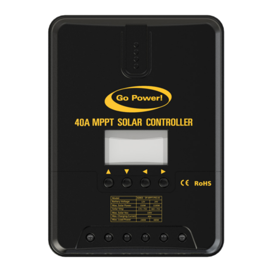
INTRODUCTION 1.4 APPEARANCE NAME NAME Charging indicator Battery “+” Battery indicator Battery “-” Load indicator Load “+” Abnormality indicator Load “-” LCD screen External temperature sensor RS232 communication Operating keys interface gpelectric.com | [page 7]... -
Page 8: Mppt Technology Instructions
INTRODUCTION 1.5 MPPT TECHNOLOGY INSTRUCTIONS Maximum Power Point Tracking (MPPT) is an advanced charging technology that more efficiently harvests power from solar panels in all conditions. It does this by continuously tracking the I-V curve of the solar array and modifying operating conditions to maximize output power. - Page 9 Shown in Figure 1-5 is a series string of solar panels and a corresponding graph that shows lower maximum power points (LMPP) and the greater maxim power point (GMPP) that will result in maximum energy transfer. The GP-MPPT-PRO series has a smart algorithm that will always choose the right peak.
-
Page 10: Charging Stage Instructions
FIGURE 1-5 Multiple peaks resulting from partial shading 1.6 CHARGING STAGE INTRODUCTIONS Maximum power point tracking is used to charge the batteries with the highest current possible, but this is only part of the equation. A battery cannot be charged at maximum power all the time for safety reasons, so multiple stages are used. These stages include bulk, boost, float and, for some types of batteries, FIGURE 1-6 Battery charging stages curve graph... -
Page 11: Installation
• Multimeter • If the solar controller was purchased with a Go Power! RV Solar Power Kit the UV resistant wire is included. Note For instructions regarding the Go Power! RV Solar Power Kit installation, please refer to the installation guide provided with the kit gpelectric.com | [page 11]... -
Page 12: Installation And Wiring
Wiring and installation must comply with national and local electrical code requirements. The wire from the solar array most commonly enters the RV through the fridge vent on the roof or by using the Go Power! Cable Entry Plate (sold separately) that allows installers to run wires through any part of the roof. PV connections should connect directly to the controller. - Page 13 PV maximum input Battery wire diameter Models at PV end Rated charge current current (mm²/AWG) (mm²/AWG) GP-MPPT-PRO-30 GP-MPPT-PRO-40 10/7 GP-MPPT-PRO-50 12/6 12/6 GP-MPPT-PRO-60 For installation safety, we recommend a wiring sequence as follows; however, wiring in other sequence instead of this one will not damage the controller.
-
Page 14: Product Operation And Display
3. PRODUCT OPERATION AND DISPLAY 3.1 LED INDICATION There are four indicators on the controller. Indicating the controller’s current PV Array Indicator charging mode Indicating the battery’s current state BAT Indicator Indicating the load’s ON/OFF and state LOAD Indicator Indicating whether the controller is ERROR Indicator functioning normally 3.1.1 PV INDICATOR... -
Page 15: Load Indicator
PRODUCT OPERATION AND DISPLAY 4. SYSTEM MAINTENANCE 3.1.3 LOAD INDICATOR LED PATTERN STATUS LOAD TURNED OFF QUICK FLASH LOAD OVER-LOADED/SHORT-CIRCUITED (cycle of 0.2s with on and off each lasting for 0.1s) STEADY ON LOAD FUNCTIONING NORMALLY 3.1.4 ERROR INDICATOR LED PATTERN STATUS SYSTEM OPERATING NORMALLY STEADY ON... -
Page 16: Startup Interface
PRODUCT OPERATION AND DISPLAY 3.3.1 STARTUP INTERFACE During startup, the 4 indicators will first flash successively, and after self-inspection, the LCD screen starts and displays the battery’s voltage level which will be either a fixed voltage selected by the user or a voltage automatically recognized 3.3.2 MAIN INTERFACE MAIN COMPONENT VOLTAGE... -
Page 17: Load Mode Setting Interface
PRODUCT OPERATION AND DISPLAY 3.4 LOAD MODE SETTING INTERFACE 3.4.1 LOAD MODES INTRODUCTION Mode Description When no sunlight is present, the solar panel voltage is lower than the light Sole light control (night- control on voltage, and after a time delay, the controller will switch on the load; time on and daytime off) when sunlight emerges, the solar panel voltage will become higher than the light control off voltage, and after a time delay, the controller will switch off the load. -
Page 18: System Parameter Settings
PRODUCT OPERATION AND DISPLAY 3.5 SYSTEM PARAMETER SETTINGS Under any interface other than load modes, press and hold the Set key to enter into the parameter setting interface. BATTERY TYPE SYSTEM VOLTAGE EQUALIZING VOLTAGE BOOST VOLTAGE OVER-DISCHARGE FLOATING CHARGING OVER-DISCHARGE RETURN VOLTAGE After entering into the setting interface, tap the Set key to switch the menu for setting, and tap the Up or Down key to increase... -
Page 19: System Maintenance
4. SYSTEM MAINTENANCE In order to maintain the best long-term performance for controller, it is recommended to conduct inspections twice a year using the following points: • Make sure the airflow around the controller is not obstructed and remove any dirt or debris from the heat sink. •... -
Page 20: Technical Parameters
5. TECHNICAL PARAMETERS 5.1 ELECTRICAL PARAMETERS ITEMS PARAMETERS GP-MPPT-PRO-30 GP-MPPT-PRO-40 GP-MPPT-PRO-50 GP-MPPT-PRO-60 MODEL 12V/24V SYSTEM VOLTAGE ZERO LOAD LOSS <10mA 9V~32V BATTERY VOLTAGE MAXIMUM PV OPEN 92V(25˚C); 100V(Lowest Ambient Temperature) CIRCUIT VOLTAGE MAXIMUM POWER (Battery voltage +2V) ~ 72V POINT VOLTAGE... -
Page 21: Battery Type Default Parameters
6. CONVERSION EFFICIENCY CURVE 5.2 BATTERY TYPE DEFAULT PARAMETERS CHARGE PARAMETERS FOR VARIOUS BATTERY TYPES SET VOLTAGE SEALED FLOODED LITHIUM CUSTOM BATTERY TYPE HIGH VOLTAGE 16.0V 16.0V 16.0V —— 9 ~ 17V DISCONNECT EQUALIZE 14.6V —— 14.8V —— 9 ~ 17V VOLTAGE BOOST 14.4V... -
Page 22: Systems
7. PRODUCT DIMENSIONS 6.2 24V SYSTEMS 7. PRODUCT DIMENSIONS GP-MPPT-PRO-40 PRODUCT DIMENSIONS HOLE POSITIONS HOLE DIAMETER Max 8 AWG APPLICABLE WIRE [page 22] | gpelectric.com... -
Page 23: Bluetooth Dongles
8.1 PRODUCT INTRODUCTION The GP-MPPT-PRO-BT-1 is compatible with Go Power!’s Bluetooth ready GP-MPPT-PRO-40 and GP-MPPT-PRO-60 solar controllers and can work seamlessly with the Go Power! Connect mobile app giving you the ability to wirelessly monitor you controller’s parameters setting and data view. -
Page 24: Product Features
BLUETOOTH DONGLES 8.5 PRODUCT FEATURES COMMUNICATION STATUS INDICATOR LIGHT MOUNTING HOLES COMMUNICATION LINE 8.6 PRODUCT DIMENSIONS 57.8 66.3 GP-MPPT-PRO-BT-1 SIDE VIEW External Dimensions: 66.3 X 51 X 15 mm Fixed holes dia: ø GP-MPPT-PRO-BT-1 FRONT VIEW [page 24] | gpelectric.com... -
Page 25: System Wiring Diagram
9. REMOTE 8.7 SYSTEM WIRING DIAGRAM Note: Cable using the standard Ethernet cable (parallel line) connect. 8.8 SPECIFICATIONS TYPE GP-MPPT-PRO-BT-1 GP-MPPT-PRO-BT-2 Input voltage 5 - 12V 5 - 12V Stand-by power 0.04W 0.04W consumption Run power consumption 0.05W 0.05W Communication distance ≤... -
Page 26: Remote
Directly powered by controller, external power supply is not needed. 10. Industrial-grade design makes it fit for various outdoor environments, and provides safe service for a long time. 9.2 APPEARANCE 40/60 Solar Controller Remote GP-MPPT-PRO-40-60-R FUNCTIONS Communication Fault Indicator Communication Connection Indicator... -
Page 27: Installation Dimensions
REMOTE 9.3 INSTALLATION DIMENSIONS Product dimensions: 96*103.82*103.82mm Installation dimensions: ø3.5mm 9.4 USAGE OF NAVIGATION KEYS The product design features 4 keys which, from left to right, are: They equal to (“Up”, “Down”, “ESC”, “OK”) OPERATION DISCRIPTION 1) When browsing a menu , tap the key for a page up, Tap, press and 2) In parameter setting, tap the key to increase the value by a minimum unit;... -
Page 28: Lcd Menu
REMOTE 9.5 LCD MENU 9.5.1 ICON DESCRIPTION ICON STATE DISCRIPTION COMMENTS Steady on Nighttime Steady on Daytime Related to charging A dynamic arrow indicates charging is Steady on in process, while a static one indicates otherwise 0 to 100% Current battery capacity 0% in slow Battery over-discharged Related to battery... -
Page 29: Menu Block Diagram
REMOTE 9.5.2 MENU BLOCK DIAGRAM MAIN MENU REAL-TIME MONITORING LOAD MODE LOAD MODE PARAMETERS SETTING STATISTIC DATA HISTORICAL DATA OF THE CURRENT DAY DEVICE INFORMATION BLUETOOTH CONNECTION STATE ® (This menu is available only to the display units with the optional Bluetooth function) ®... -
Page 30: Real-Time Monitoring
REMOTE 9.6 REAL-TIME MONITORING (This menu is contained in and supplementary to information of the main menu) In the MAIN MENU, tap to enter into this menu; continue to tap to switch between menus; or tap to return to the MAIN MENU. (Refer to 9.4 USAGE OF NAVIGATION KEYS for operation) PROJECT OR PAGE DECRIPTION... -
Page 31: System Parameter Settings
REMOTE 9.7 SYSTEM PARAMETER SETTINGS MENU DISPLAYED ITEM/ PARAMETER AND PAGE ITEM TO SET NOTES LEVEL PARAMETER SETTING RANGE 12V, 12V system 24V, 24V system Battery system voltage BatSysVol 36V, 36V system 48V, 48V system AUTO, auto recognition SLD, sealed lead-acid battery FLD, open lead-acid battery Battery type... -
Page 32: Controller Charging And Discharging Related Parameter Settings
REMOTE 1) In this manual, “n” assigned with a value of 1, 2, 3 or 4 denotes a battery system of 12V, 24V, Note 36V or 48V accordingly. 2) Before setting parameters, first refer to the User Manual of the corresponding controller. As some parameters are not settable, operation of setting these parameters on the display unit will be deemed as invalid or impossible by the controller. -
Page 33: Controller Abnormality Voice Alarm - On/Off Setting
REMOTE 9.7.3 CONTROLLER ABNORMALITY VOICE ALARM - ON/OFF SETTING BUZZER STATE ALARM TYPE No Alarm System running well Battery over-discharge, Load short circuit/overload, controller Alarming: 1 min or battery over-temperature Alarming: 15 sec Battery under-voltage Battery over-voltage,solar panel reverse connection,solar panel Alarming: Persistent over voltage CHARACTER DISPLAYED... -
Page 34: Statistic Data
REMOTE • pressing and holding the key will not switch on/ off the load. For parameters on the current menu, those highlighted are settable, while those underlined are not This parameter is ineffective for controllers without loads. Note MODE LOAD MODE DESCRIPTIONS CHARACTERS The solar panel voltage is lower than the light control on... -
Page 35: Device Information
REMOTE MENU DISPLAYED ITEM/ PAGE DESCRIPTION LEVEL PARAMETER XXXX: select the historical data of day xxxx (counting 2nd- backwards) <History Data> Level 0000: the current day xxxx Days Ago Menus 0001: yesterday 0002: the day before yesterday MinBatVol: 11.5V The selected day’s min. battery voltage MaxBatVol: 11.6V The selected day’s max. -
Page 36: Bluetooth ® Connection Status
9.8.3 BLUETOOTH CONNECTION STATUS ® Bluetooth icon ® Indicates Bluetooth ® connection status When “Disconnect” is displayed on the screen, it indicates no Bluetooth device is currently connected. When “Connected”, it indicates some Bluetooth device has been connected. Bluetooth functions and this menu are only available to the “RM-5B” display unit, and not the “RM-5” unit. The App is only compatible with Android phones with an OS version of 4.3 or above and iphones. -
Page 37: Fault Indication And Communication Indication
9.9 FAULT INDICATION AND COMMUNICATION INDICATION 40/60 Solar Controller Remote GP-MPPT-PRO-40-60-R Communication fault indicator Communication connection indicator MENU LEVEL STATE DESCRIPTION Steady off The controller system is norma.l System fault indicator Abnormality occurs to the controller system (Please check Quick flashing the error code). - Page 38 © 2020 Go Power! Worldwide Technical Support and Product Information gpelectric.com Go Power! 201-710 Redbrick Street Victoria, BC, V8T 5J3 Tel: 1.866.247.6527 82803_MAN_GP-MPPT-PRO-40_RevA...
Need help?
Do you have a question about the MPPT-PRO and is the answer not in the manual?
Questions and answers