Table of Contents
Advertisement
Quick Links
GP-PWM-10
User Manual
10 AMP PWM SOLAR CONTROLLER
© 2015 Go Power!® By Carmanah Technologies
Worldwide Technical Support and
Product Information
Carmanah Technologies Corporate Headquarters
250 Bay St, Victoria, BC Canada V9A 3K5
Tel: 1.877.722.8877
77726_MAN_GP-PWM-10_RevD
gpelectric.com
™
powered by
®
Advertisement
Table of Contents

Related Manuals for Go Power GP-PWM-10


Summary of Contents for Go Power GP-PWM-10
- Page 1 GP-PWM-10 ™ User Manual 10 AMP PWM SOLAR CONTROLLER © 2015 Go Power!® By Carmanah Technologies Worldwide Technical Support and Product Information gpelectric.com Carmanah Technologies Corporate Headquarters ® 250 Bay St, Victoria, BC Canada V9A 3K5 Tel: 1.877.722.8877 77726_MAN_GP-PWM-10_RevD powered by...
-
Page 3: Table Of Contents
Contents 1. Installation Overview ................... 4 Introduction ....................4 1.2 Specifications ..................... 5 2. Warnings ......................6 3. Tools and Materials Needed ..............7 4. Choosing a Location ..................7 5. Installation Instructions ................7 6. Wiring Diagram ....................9 7. -
Page 4: Installation Overview
Modulation (PWM) technology and a unique four stage charging system that includes an automatic equalize setting to charge and protect your battery bank (for flooded batteries only). The GP-PWM-10 features an LCD digital display that shows the charge current of the solar array, system battery voltage and battery capacity. The GP-PWM-10 also features Maximum Power Boost Technology™ for an automatic bulk charge at any stage of the charge cycle. -
Page 5: Specifications
The total rated Maximum Power Current (Imp) of the PV input should not exceed 10 amps. The GP-PWM-10 will limit PV current above 10 Amps. Although the GP-PWM-10 will accept PV current greater than 10 Amps for a short duration, damage may occur if the GP-PWM-10 operates continuously with greater than 10 Amps of PV input. -
Page 6: Warnings
Maximum Power Current (Imp) of the solar Do not exceed the PV strings in parallel. The resulting system Imp GP-PWM-10 amp current is not to exceed 10A. The voltage of the current and max array is the rated open circuit voltage (Voc) of voltage ratings the PV array and is not to exceed 28V. -
Page 7: Tools And Materials Needed
Go Power! RV Solar Power Kit installation, please refer to the Installation Guide provided with the Kit. 4. Choosing a Location The GP-PWM-10 is designed to be mounted against a wall, out of the way but easily visible. The GP-PWM-10 should be: •... - Page 8 Wiring the GP-PWM-10. Wire the GP-PWM-10 according to the wiring schematic in Section 6. Run wires from the solar array and the batteries to the location of the GP-PWM-10. Keep the solar array covered with an opaque material until all wiring is completed.
-
Page 9: Wiring Diagram
Mounting the GP-PWM-10. Mount the GP-PWM-10 to the wall using the included four mounting screws. IMPORTANT: You must set the battery type on the GP-PWM-10 before you begin to use the controller (follow steps in Section 7). The default battery setting is for AGM batteries. -
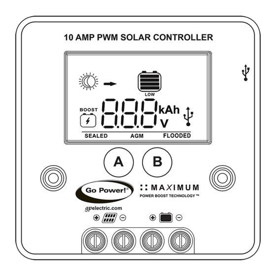
Page 10: Display Symbols
7. Display Symbols 1. Sun = Daytime: PV Charge Current 4.USB Charging On Moon = Nighttime: No Charge Current 2. Battery State of Charge 5. Battery Type Profiles 3. Low Battery Voltage 6. Controller tries to keep battery at boost voltage or higher (automatic setting) Battery State of Charge Chart Shows only after full Boost <= 11.0V... -
Page 11: Operating Instructions
8. Operating Instructions 8.1 Power Up When the GP-PWM-10 is connected to the battery, the controller will go into Power Up mode. Icons Displayed: All segments of the numerical display blink Depending on the battery voltage when the GP-PWM-10 Power Up occurs, the controller may do a Boost Charge or quickly go into Float Charge. -
Page 12: Battery Charging Profile Chart
Note battery designations. Choose the charging profile that works best with your battery manufacturer’s recommendations. Auto Equalize: The GP-PWM-10 has an automatic equalize feature that will charge and recondition your batteries once a month at a higher Note voltage to ensure that any excess sulfation is removed. Auto equalize is only available for Flooded batteries. -
Page 13: Viewing The Controller Display Information
Operating Instructions 8.4 Viewing the Controller Display Information To toggle between Battery Voltage, PV Charging Current and Battery State of Charge (SOC), press the B Button. Battery Voltage Screen Push the B Button to show the battery voltage. Icons Displayed: Battery SOC, Sun, Volt Symbol (V) Battery Current Screen Push the B Button to show the PV... -
Page 14: Errors
Icons Displayed: Amp Hour Symbol (Ah), Arrow, Battery SOC, Sun 8.5 Errors Over Voltage If the GP-PWM-10 experiences a battery over voltage (15.5V), the controller will stop operating and the display will begin to flash with all icons. The controller will resume operating when the error is cleared. -
Page 15: Usb Charging
9. USB Charging The GP-PWM-10 offers a standard USB connector for delivering 5V to small mobile appliances such as cell phones, tablets, small music players. This charging port is capable of supplying up to 800 mA of current. The USB charging port is always active when the USB symbol appears on the display. -
Page 16: Frequently Asked Questions (Faqs)
3. My voltmeter shows a different reading than the GP-PWM-10 display The meter value on the GP-PWM-10 display is an approximate reading intended for indication purposes only. There is an approximate 0.1 volt inherent error present that may be accentuated when compared with readings from another voltmeter. -
Page 17: Troubleshooting Problems
11. Troubleshooting Problems How to Read this Section Troubleshooting Problems is split into three sub-sections, grouped by symptoms involv- ing key components. A multimeter or voltmeter may be required for some procedures listed. It is imperative that all electrical precautions outlined in this manual are followed. - Page 18 Contact the Go Power! 4. Blown diode in solar Technical Support team as module when two 4. Disconnect array wires from listed in section 10.1 for...
-
Page 19: Limited Warranty
Go Power! electronic products are non-repairable. Go Power! does not perform repairs on its products nor does it contract out those repairs to a third party. Go Power! does not supply schematics or replacement parts for any of its electronic products.
Need help?
Do you have a question about the GP-PWM-10 and is the answer not in the manual?
Questions and answers