
Related Manuals for Go Power MAXIMUM GP-PWM-10


Summary of Contents for Go Power MAXIMUM GP-PWM-10
- Page 1 GP-PWM-10 _________________________________________________________________________________ User Manual © 2017 Go Power!®...
- Page 2 GP-PWM-10 _________________________________________________________________________________ © 2017 Go Power!®...
-
Page 3: Table Of Contents
GP-PWM-10 _________________________________________________________________________________ Contents Installation Overview Introduction Specifications Warnings Tools and Materials Needed Choosing a Location Installation Instructions Wiring Diagram Operating Instructions Power Up Setting the Battery Charging Profile Battery Charging Profile Chart Viewing the Controller Display Information Resetting the ampere hours charged Errors Display Symbols USB Charging... -
Page 4: Installation Overview
GP-PWM-10 _________________________________________________________________________________ 12.0 Limited Warranty 12.1 Repair and Return Information 1.0 Installation Overview 1.1 Introduction A Solar Controller (or Charge Controller / Regulator) is an essential component of your photovoltaic solar system. The Controller maintains the life of the battery by protecting it from overcharging. When your battery has reached a 100% state of charge, the Controller prevents overcharging by limiting the current flowing into the batteries from your solar array. -
Page 5: Specifications
GP-PWM-10 _________________________________________________________________________________ 1.2 Specifications Description Value Dimensions (H x W x D): Nominal System Voltage 100 x 102 x 29 mm 3.94 x 4.02 x 1.14 in Max. Solar Array Current 10A (a mperage is reduced above 50°C) Weight: 178 g / 6.3 oz Battery Voltage Range 6V –... -
Page 6: Warnings
GP-PWM-10 _________________________________________________________________________________ 2.0 Warnings Electricity can be very dangerous. Installation Disconnect all should be performed only by a licensed power sources electrician or qualified personnel. Observe all safety precautions of the battery Battery and manufacturer when handling or working around batteries. When charging, batteries wiring safety produce hydrogen gas, which is highly explosive. -
Page 7: Choosing A Location
GP-PWM-10 _________________________________________________________________________________ 4.0 Choosing a Location The GP-PWM-10 is designed to be mounted against a wall, out of the way but easily visible. The GP-PWM-10 should be: • Mounted as close to the battery as possible • Mounted on a vertical surface to optimize cooling of the unit •... - Page 8 GP-PWM-10 _________________________________________________________________________________ Wire Strip Gauge You will find a strip gauge diagram on the back of the GP-PWM-10, which helps you to strip your wires to the correct length. Insert wire into the concave slot of the strip gauge until it meets the back of the Strip Gauge slot.
-
Page 9: Wiring Diagram
GP-PWM-10 _________________________________________________________________________________ With battery power attached, the controller should power up and display information. Connect the solar wiring to the controller and remove the opaque material from the solar array. The negative solar array and battery wiring must be connected directly to the controller for proper operation. -
Page 10: Operating Instructions
GP-PWM-10 _________________________________________________________________________________ 7.0 Operating Instructions 7.1 Power Up When the GP-PWM-10 is connected to the battery, the controller will go into Power Up mode. Icons Displayed: All segments of the numerical display; Backlight blinks Depending on the battery voltage when the GP-PWM- 10 Power Up occurs, the controller may do a Boost Charge or quickly go into... -
Page 11: Battery Charging Profile Chart
GP-PWM-10 _________________________________________________________________________________ To confirm the battery profile, press and hold the A Button for 3 seconds. Non-volatile memory: Any settings made on the GP- PWM-10 will be saved even when the power has been disconnected from the controller. Refer to the Battery Charge Profile Chart below for details on each profile. -
Page 12: Viewing The Controller Display Information
GP-PWM-10 _________________________________________________________________________________ Auto Equalize: The GP-PWM-10 has an automatic equalize feature that will charge and recondition your batteries once a month at a higher voltage to ensure that any excess sulfation is removed. This feature is only available when Flooded batteries are selected. - Page 13 GP-PWM-10 _________________________________________________________________________________ Push the B Button to show the battery state of charge (shown as a percentage). Icons Displayed: Battery SOC, Percent Symbol (%) Push the B Button to show the number of amp hours charged since the last reset. Icons Displayed: Amp hours charged, Amp hour symbol (Ah) or Kiloamp hour symbol (kAh)
-
Page 14: Resetting The Ampere Hours Charged
GP-PWM-10 _________________________________________________________________________________ 7.5 Resetting the ampere hours charged To reset the count of ampere hours charged, toggle to the ampere hours charged. Press and hold the A Button for 6 seconds to reset the counter to zero. 7.6 Errors Over Voltage If the GP-PWM-10 experiences a battery over voltage (15.5V), the controller will stop operating... -
Page 15: Display Symbols
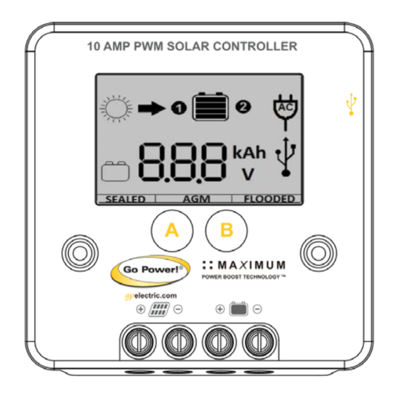
GP-PWM-10 _________________________________________________________________________________ 8.0 Display Symbols Symbol Indicator For: Day Time: PV Charge Current Night Time Battery Voltage Battery State of Charge SEALED Sealed/Gel AGM/LFP FLOODED Flooded Other Symbols USB charger on (When charger is off, no symbol will show) Controller tries to keep battery at BOOST Boost Voltage or higher Battery voltage is lower than 11.0V... -
Page 16: Usb Charging
GP-PWM-10 _________________________________________________________________________________ Battery State of Charge Symbol Battery Voltage Shows only after full Boost or Equalization Cycle >= 12.6V >= 11.8 -12.6V > 11.0 -11.8V <= 11.0V Shows only after full Boost 100% or Equalization Cycle ���������������������������� ������������ ���� ������������ − 11.0���� >= 12.8V ������������... -
Page 17: Frequently Asked Questions (Faqs)
GP-PWM-10 _________________________________________________________________________________ The controller disables the USB charger automatically if the battery voltage drops below 11.0V. If there is enough current from the PV panel/array available to charge the Battery to above 12.8V, the USB terminal will be enabled again. Warning: Do not connect the charging device anywhere else! USB-Negative contact... -
Page 18: Troubleshooting Problems
GP-PWM-10 _________________________________________________________________________________ There may be a slight difference between the battery voltage displayed on the GP-PWM-10 display and the battery voltage measured at the battery terminals. When troubleshooting using a voltmeter, check both the battery voltage at the GP-PWM-10 controller terminals and battery voltage at the battery terminals. -
Page 19: Problems With Voltage
GP-PWM-10 _________________________________________________________________________________ 3. For the solar array, repeat steps 1 and 2 substituting all battery terminals with solar array terminals. Remedy: Check all connections from the controller to the battery including checking for correct wire polarity. Check that all connections are clean, tight, and secure. -
Page 20: Problems With Current
GP-PWM-10 _________________________________________________________________________________ Remedy: Check all connections from the controller to the battery including checking for correct wire polarity. Check that all connections are clean, tight, and secure. Shorten the distance from the controller to battery or obtain larger gauge wire. It is also possible to double up the existing gauge wire (i.e. - Page 21 GP-PWM-10 _________________________________________________________________________________ (2) Incorrect series/parallel configuration and/or wiring connections and/or wire gauge. (3) Dirty or shaded module or lack of sun. (4) Blown diode in solar module when two or more modules are connected in parallel. How to tell: (1) Battery State of Charge screen is close to 100% and the Sun and Battery icon are present with an arrow in between.
- Page 22 GP-PWM-10 _________________________________________________________________________________ 12.0 Limited Warranty 1. Go Power! warrants the GP-PWM-10 for a period of five (5) years from the date of shipment from its factory. This warranty is valid against defects in materials and workmanship for the five(5) year warranty period. It is not valid against defects resulting from, but not limited to: •...
- Page 23 GP-PWM-10 _________________________________________________________________________________ © 2017 Go Power!®...
- Page 24 GP-PWM-10 _________________________________________________________________________________ © 2017 GO POWER!® MOBI_MAN_GP-PWM-10_vF electric.com © 2017 Go Power!®...
Need help?
Do you have a question about the MAXIMUM GP-PWM-10 and is the answer not in the manual?
Questions and answers