
Related Manuals for Go Power GP-PWM-30-SB


Summary of Contents for Go Power GP-PWM-30-SB
- Page 1 GP-PWM-30-SB ________________________________________________________________________ GP-PWM-30-SB User Manual 30 AMP PWM SOLAR CONTROLLER © 2019 Go Power!
-
Page 2: Table Of Contents
Display Symbols USB Charging 10.0 Frequently Asked Questions (FAQs) 11.0 Troubleshooting Problems 11.1 Problems with the Display 11.2 Problems with Voltage 11.3 Problems with Current 12.0 Limited Warranty 12.1 Repair and Return Information 13.0 Installation Template © 2019 Go Power! -
Page 3: Installation Overview
1.2 System Voltage and Current The GP-PWM-30-SB is intended for use at 12 VDC nominal system voltage and is rated for a maximum continuous DC input current of 37.5A and input voltage of 35VDC. -
Page 4: Low Voltage Disconnect Function (Usb Port)
Voltage, Battery State of Charge, and Amp Operating Consumption 6 mA Hours Charged Since (Display backlight off) Last Reset Battery Types Supported Vented and Sealed Lead Acid • Reverse Polarity (GEL, AGM, Flooded, Lithium Protected (LFP), etc.) © 2019 Go Power! - Page 5 - 40 to 85°C / - 40 to 185°F Display Operating - 10 to 55°C / 14 to 131°F Temperature Humidity 99% N.C. Protection Battery Reverse Polarity, Solar Array Reverse Polarity, Over Temperature, PV Short Circuit, Over Current © 2019 Go Power!
-
Page 6: Important Safety Instructions
GP-PWM-30-SB 2.0 IMPORTANT SAFETY INSTRUCTIONS SAVE THESE INSTRUCTIONS THIS MANUAL CONTAINS IMPORTANT INSTRUCTIONS FOR MODEL GP-PWM-30-SB THAT SHOULD BE FOLLOWED DURING INSTALLATION AND MAINTENANCE OF THE GP-PWM-30-SB. Electricity can be very dangerous. Installation Disconnect all should be performed only by a licensed power sources electrician or qualified personnel. -
Page 7: Tools And Materials Needed
The wire from the solar array most commonly enters the RV through the fridge vent on the roof or by using the Go Power! Cable Entry Plate (sold separately) that allows installers to run wires through any part of the roof. - Page 8 GP-PWM-30-SB 2. Complete the installation of the solar modules. If this GP-PWM-30-SB was purchased as part of a Go Power! Solar Power Kit, follow the Installation Guide provided. Otherwise, follow manufacturer’s instructions for solar module mounting and wiring. The maximum current of the solar system is Do not exceed the sum of parallel-connected PV module–...
- Page 9 Wiring the GP-PWM-30-SB. Wire the GP-PWM-30-SB according to the wiring schematic in Section 6. Run wires from the solar array and the batteries to the location of the GP-PWM-30-SB. Keep the solar array covered with an opaque material until all wiring is completed.
-
Page 10: Wiring Diagram
IMPORTANT: This diagram is valid only for version 1.5 and newer. Version 1.4 and older have different terminal locations. The GP-PWM-30-SB Maximum 37.5A rating is based on a 30 amp total maximum short circuit current rating (Isc) from the parallel solar modules nameplate ratings. -
Page 11: Operating Instructions
GP-PWM-30-SB 7.0 Operating Instructions 7.1 Power Up When the GP-PWM-30-SB is connected to the battery, the controller will go into Power Up mode. Icons Displayed: All segments of the numerical display; backlight blinks. Depending on the battery voltage when the GP-PWM-30-SB Power Up occurs, the controller may do a Boost Charge or quickly go into Float Charge. -
Page 12: Setting The Battery Charging Profile
Sealed/Gel, AGM/Lithium (LFP) or Flooded. To confirm the battery profile, press and hold the A Button for 3 seconds. Non-volatile memory: Any settings made on the GP-PWM-30-SB will be saved even when the power has been disconnected from the controller. -
Page 13: Viewing The Controller Display Information
Auto Equalize: The GP-PWM-30-SB has an automatic equalize feature that will charge and recondition your batteries at least once a month at a higher voltage to ensure that any excess sulfation is removed. - Page 14 GP-PWM-30-SB Push the B Button to show the battery voltage. Icons Displayed: Battery SOC, Volt Symbol (V) Push the B Button to show the PV charging current. Icons Displayed: Ampere Symbol (A), Battery SOC © 2019 Go Power!
- Page 15 A value of 100% will only be displayed after a Boost or Equalize charge completes. Push the B Button to show the number of amp hours charged since the last reset. Icons Displayed: Amp hours charged, Amp hour symbol (Ah) or kiloamp hour symbol (kAh) © 2019 Go Power!
-
Page 16: Resetting The Ampere Hours Charged
7.6 Errors Over Voltage If the GP-PWM-30-SB experiences a battery over voltage (15.5V), the controller will stop operating, and the display will begin to flash with all icons. The controller will resume operating when the error is cleared. -
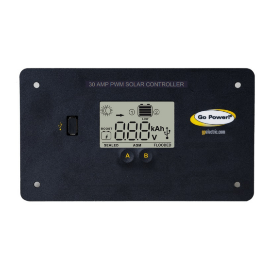
Page 17: Display Symbols
9 volts. Icons Displayed: Battery SOC Symbol, LOW 8.0 Display Symbols Symbol Indicator For: Day Time: PV Charge Current Night Time Battery Voltage Battery State of Charge SEALED Sealed/Gel AGM/LFP AGM/LFP FLOODED Flooded © 2019 Go Power! - Page 18 > 11.0 -11.8 VDC <= 11.0 VDC Shows only after full Boost 100% or Equalization Cycle >= 12.8 VDC ���������������������������� ������������ ���� ������������ − 11.0���� ������������ = ∗ 90% 1.8���� <12.8 VDC and > 11.0 <= 11.0 VDC © 2019 Go Power!
-
Page 19: Usb Charging
GP-PWM-30-SB USB Charging The GP-PWM-30-SB offers a standard USB connector for delivering 5.0 VDC to small mobile appliances such as cell phones, tablets or small music players. This charging port is capable of supplying up to 1500 mA of current. - Page 20 There may be a slight difference between the battery voltage displayed on the GP-PWM-30-SB display and the battery voltage measured at the battery terminals. When troubleshooting using a voltmeter, check both the battery voltage at the GP-PWM-30-SB controller terminals and battery voltage at the battery terminals.
-
Page 21: Troubleshooting Problems
Remedy: Check all connections from the controller to the battery including checking for correct wire polarity. Check that all connections are clean, tight, and secure. Ensure the battery voltage is above 6 volts. © 2019 Go Power! -
Page 22: Problems With Voltage
It is also possible to double up the existing gauge wire (i.e. two wire runs) to simulate a larger gauge wire. Voltage Reading: Controller flashes entire LCD for battery overvoltage Time of Day: Daytime/Nighttime © 2019 Go Power! -
Page 23: Problems With Current
2. With the solar array in sunlight, check the voltage at the controller solar array terminals with a voltmeter. If there is no reading at the controller solar array terminals, the problem is somewhere in the wiring from the solar array to the controller. © 2019 Go Power! - Page 24 VDC. If you have more than one solar module, you will need to conduct this test between the positive and negative terminals of each module junction box with either the positive or the negative wires disconnected from the terminal. © 2019 Go Power!
-
Page 25: Limited Warranty
12.0 Limited Warranty Go Power! warrants the GP-PWM-30-SB for a period of five (5) years from the date of shipment from its factory. This warranty is valid against defects in materials and workmanship for the five (5) year warranty period. -
Page 26: Installation Template
GP-PWM-30-SB 13.0 Installation Template Use the template below for flush mounting the controller. © 2019 Go Power! - Page 27 GP-PWM-30-SB © 2019 GO POWER!® MOBI_MAN_GP-PWM-30-SB_RevB gpelectric.com © 2019 Go Power!
Need help?
Do you have a question about the GP-PWM-30-SB and is the answer not in the manual?
Questions and answers