Table of Contents
Advertisement
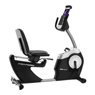
Model No. PFEVEX74918.0
Serial No.
Write the serial number in the space
above for reference.
CUSTOMER SERVICE
UNITED KINGDOM
Call: 0330 123 1045
From Ireland: 053 92 36102
Website: www.iconsupport.eu
E-mail: csuk@iconeurope.com
Write:
ICON Health & Fitness, Ltd.
Unit 1D, The Gateway
Fryers Way, Silkwood Park
OSSETT
WF5 9TJ
UNITED KINGDOM
AUSTRALIA
Call: 1800 993 770
E-mail: australiacc@iconfitness.com
Write:
ICON Health & Fitness
PO Box 635
WINSTON HILLS NSW 2153
AUSTRALIA
CAUTION
Read all precautions and
instructions in this manual before
using this equipment. Keep this
manual for future reference.
Serial
Number
Decal
USER'S MANUAL
iconeurope.com
Advertisement
Table of Contents

Related Manuals for Pro-Form 325 CSX+


Summary of Contents for Pro-Form 325 CSX+
- Page 1 Model No. PFEVEX74918.0 Serial No. USER’S MANUAL Write the serial number in the space above for reference. Serial Number Decal CUSTOMER SERVICE UNITED KINGDOM Call: 0330 123 1045 From Ireland: 053 92 36102 Website: www.iconsupport.eu E-mail: csuk@iconeurope.com Write: ICON Health & Fitness, Ltd. Unit 1D, The Gateway Fryers Way, Silkwood Park OSSETT...
-
Page 2: Table Of Contents
TABLE OF CONTENTS WARNING DECAL PLACEMENT ............. . .2 IMPORTANT PRECAUTIONS . -
Page 3: Important Precautions
IMPORTANT PRECAUTIONS WARNING: To reduce the risk of serious injury, read all important precautions and instructions in this manual and all warnings on your exercise bike before using your exercise bike. ICON assumes no responsibility for personal injury or property damage sustained by or through the use of this product. -
Page 4: Before You Begin
BEFORE YOU BEGIN Thank you for selecting the new PROFORM reading this manual, please see the front cover of this ® 325 CSX + exercise bike. Cycling is an effective manual. To help us assist you, note the product model exercise for increasing cardiovascular fitness, build- number and serial number before contacting us. -
Page 5: Part Identification Chart
PART IDENTIFICATION CHART Use the drawings below to identify the small parts needed for assembly. The number in parentheses below each drawing is the key number of the part, from the PART LIST near the end of this manual. The number following the key number is the quantity needed for assembly. -
Page 6: Assembly
ASSEMBLY • Assembly requires two persons. In addition to the included tool(s), assembly requires the following tools: • Place all parts in a cleared area and remove the one Phillips screwdriver packing materials. Do not dispose of the packing materials until you finish all assembly steps. one adjustable wrench •... - Page 7 3. Orient the Front Stabilizer (2) as indicated by the sticker. While a second person lifts the front of the Frame (1), attach the Front Stabilizer (2) to the Frame with two M10 x 80mm Screws (21). 4. Orient the Adjustment Lever (6) as shown. Attach the Adjustment Lever (6) to the Brake Axle (37) with two M6 x 16mm Screws (33), two M6 Split Washers (34), and two M6...
- Page 8 6. Orient the Seat (10) and the Seat Frame (9) as shown. Attach the Seat (10) to the Seat Frame (9) with four M6 x 40mm Screws (27); start all the Screws, and then tighten them. 7. Attach the Seat Frame (9) to the Seat Carriage (7) with four M8 x 40mm Screws (28);...
- Page 9 8. Orient the Backrest (11) as shown. Attach the Backrest (11) to the Backrest Frame (8) with two M6 x 40mm Screws (27). 9. Remove the Accessory Tray (5) from the Left and Right Front Shields (57, 58). Set the Accessory Tray aside.
- Page 10 10. Tip: Avoid pinching the Main Wire (77). Hold the Upright (4) against the Frame (1). Attach the Upright with four M8 x 15mm Screws (24); start all the Screws, and then tighten them. Next, orient the Accessory Tray (5) and the Console Cover (16) as shown.
- Page 11 12. While a second person holds the Console (15) near the Handlebar (14), connect the wires on the Console to the Main Wire (77) and the Pulse Wire (50). Then, insert the excess wire into the Handlebar (14). Tip: Avoid pinching the wires. Attach the Console (15) to the Handlebar (14) with four M4 x 16mm Screws (49);...
- Page 12 14. Identify the Right Pedal (13). Using an adjustable wrench, firmly tighten the Right Pedal clock- wise into the Right Crank Arm (71). Firmly tighten the Left Pedal (not shown) counterclockwise into the Left Crank Arm (not shown). IMPORTANT: You must turn the Left Pedal counterclockwise to attach it.
-
Page 13: How To Use The Exercise Bike
HOW TO USE THE EXERCISE BIKE HOW TO PLUG IN THE POWER ADAPTER HOW TO ADJUST THE SEAT IMPORTANT: If the exercise bike has been exposed The seat can be to cold temperatures, allow it to warm to room tem- adjusted forward perature before you plug in the power adapter (A). - Page 14 HOW TO LEVEL THE EXERCISE BIKE HOW TO USE THE TABLET HOLDER If the exercise bike IMPORTANT: The tablet holder (G) is designed for use with most full-size tablets. Do not place rocks slightly on your any other electronic device or object in the tablet floor during use, turn one or both of the holder.
- Page 15 CONSOLE DIAGRAM FEATURES OF THE CONSOLE a target pedaling speed as it guides you through an effective workout. The advanced console offers an array of features designed to make your workouts more effective and You can even listen to your favorite workout music or enjoyable.
- Page 16 HOW TO USE THE MANUAL MODE approximate number of calories you have burned. When calorie workouts are selected, the approxi- 1. Begin pedaling or press any button on the mate number of calories that remain to be burned console to turn on the console. in the workout.
- Page 17 Scan mode—The console also has a scan mode To pause the console, simply stop pedaling or that will display workout information in a repeating press the End button. When the console is paused, cycle. To turn on the scan mode, press the Scan the time will flash in the display.
- Page 18 When your pulse is detected, your heart rate will be If the pedals do not move for several minutes and shown in the display. For the most accurate heart the buttons are not pressed, the console will turn rate reading, hold the contacts for at least 15 off and the display will be reset.
- Page 19 HOW TO USE AN ONBOARD WORKOUT As you exercise, you will be prompted to keep your pedaling speed near the target speed for the 1. Begin pedaling or press any button on the current segment. When the words TOO SLO console to turn on the console.
- Page 20 Time Workouts—Each Time workout is divided THE OPTIONAL CHEST HEART RATE MONITOR into one-minute segments. Adjust the resistance level and your pedaling speed as desired during Whether your each segment of a Time workout. goal is to burn fat or to The workout will continue in this way until the last strengthen your segment ends.
- Page 21 HOW TO CONNECT YOUR TABLET TO THE 5. Disconnect your tablet from the console if CONSOLE desired. The console supports Bluetooth connections to tab- To disconnect your tablet from the console, first lets via the iFit–Smart Cardio Equipment app and to select the disconnect option in the iFit–Smart compatible heart rate monitors.
- Page 22 HOW TO CHANGE CONSOLE SETTINGS Total Distance—The letters MI or KM will appear in the display. The display will show the total 1. Select the settings mode. distance (in miles or kilometers) that the exercise bike has been pedaled. To select the settings mode, press the Settings button.
-
Page 23: Maintenance And Troubleshooting
MAINTENANCE AND TROUBLESHOOTING MAINTENANCE Next, locate the Reed Switch (78). Slightly loosen the M4 x 12mm Washer Head Screw (65). Regular maintenance is important for optimal performance and to reduce wear. Inspect and properly tighten all parts each time the exercise bike is used. Replace any worn parts immediately. -
Page 24: Exercise Guidelines
EXERCISE GUIDELINES Burning Fat—To burn fat effectively, you must exer- WARNING: cise at a low intensity level for a sustained period of Before beginning this time. During the first few minutes of exercise, your or any exercise program, consult your physi- body uses carbohydrate calories for energy. -
Page 25: Part List
PART LIST Model No. PFEVEX74918.0 R0818A Key No. Qty. Description Key No. Qty. Description Frame M8 x 20mm Screw Front Stabilizer M6 x 13mm Screw Rear Stabilizer Upper Roller Upright Lower Roller Accessory Tray Roller Axle Adjustment Lever Carriage Rail Seat Carriage Carriage Rail Bumper Backrest Frame... -
Page 26: Exploded Drawing
EXPLODED DRAWING A Model No. PFEVEX74918.0 R0818A... - Page 27 EXPLODED DRAWING B Model No. PFEVEX74918.0 R0818A...
-
Page 28: Ordering Replacement Parts
ORDERING REPLACEMENT PARTS To order replacement parts, please see the front cover of this manual. To help us assist you, be prepared to provide the following information when contacting us: • the model number and serial number of the product (see the front cover of this manual) •...
Need help?
Do you have a question about the 325 CSX+ and is the answer not in the manual?
Questions and answers