Advertisement
Table of Contents
- 1 Table of Contents
- 2 Warning Decal Placement
- 3 Important Precautions
- 4 Before You Begin
- 5 Part Identification Chart
- 6 Assembly
- 7 Carriage (7) with an M8 X 20Mm Screw (42) and an M8 X 30Mm Screw (41)
- 8 How to Use the Exercise Bike
- 9 Maintenance and Troubleshooting
- 10 Exercise Guidelines
- 11 Part List
- 12 Exploded Drawing
- 13 Ordering Replacement Parts
- 14 Recycling Information
- Download this manual
Model No. PFEVEX74914.0
Serial No.
USER'S MANUAL
Write the serial number in the space
above for reference.
Serial Number
Decal
CUSTOMER SERVICE
UNITED KINGDOM
Call: 08457 089 009
From Ireland: 053 92 36102
Website: www.iconsupport.eu
E-mail: csuk@iconeurope.com
Write:
ICON Health & Fitness, Ltd.
Unit 1D, The Gateway
Fryers Way, Silkwood Park
OSSETT
WF5 9TJ
UNITED KINGDOM
AUSTRALIA
Call: 1800 993 770
E-mail: australiacc@iconfitness.com
Write:
ICON Health & Fitness
PO Box 635
WINSTON HILLS NSW 2153
AUSTRALIA
CAUTION
Read all precautions and instruc-
tions in this manual before using
this equipment. Keep this manual
for future reference.
www.iconeurope.com
Advertisement
Table of Contents

Related Manuals for Pro-Form 350 CSX


Summary of Contents for Pro-Form 350 CSX
- Page 1 Model No. PFEVEX74914.0 Serial No. USER’S MANUAL Write the serial number in the space above for reference. Serial Number Decal CUSTOMER SERVICE UNITED KINGDOM Call: 08457 089 009 From Ireland: 053 92 36102 Website: www.iconsupport.eu E-mail: csuk@iconeurope.com Write: ICON Health & Fitness, Ltd. Unit 1D, The Gateway Fryers Way, Silkwood Park OSSETT...
-
Page 2: Table Of Contents
TABLE OF CONTENTS WARNING DECAL PLACEMENT ............. . .2 IMPORTANT PRECAUTIONS . -
Page 3: Important Precautions
IMPORTANT PRECAUTIONS WARNING: To reduce the risk of serious injury, read all important precautions and instructions in this manual and all warnings on your exercise bike before using your exercise bike. ICON assumes no responsibility for personal injury or property damage sustained by or through the use of this product. -
Page 4: Before You Begin
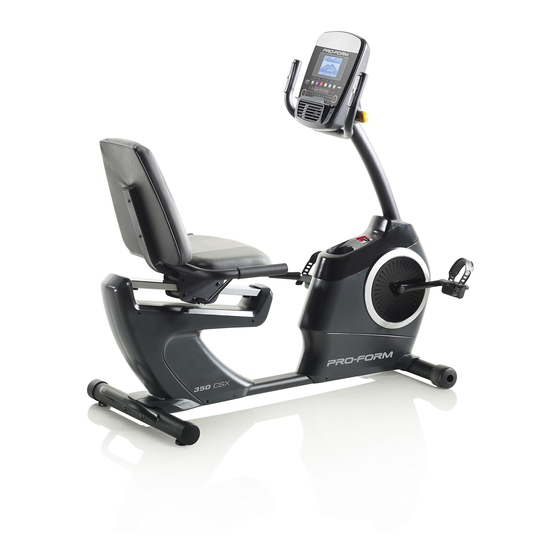
The ance, and toning the body. The 350 CSX exercise bike model number and the location of the serial number provides a selection of features designed to make your decal are shown on the front cover of this manual. -
Page 5: Part Identification Chart
PART IDENTIFICATION CHART Use the drawings below to identify the small parts needed for assembly. The number in parentheses below each drawing is the key number of the part, from the PART LIST near the end of this manual. The number following the key number is the quantity needed for assembly. -
Page 6: Assembly
ASSEMBLY • Assembly requires two persons. In addition to the included tool(s), assembly requires the following tools: • Place all parts in a cleared area and remove the one Phillips screwdriver packing materials. Do not dispose of the packing materials until you finish all assembly steps. one adjustable wrench •... -
Page 7: Carriage (7) With An M8 X 20Mm Screw (42) And An M8 X 30Mm Screw (41)
3. Set a sturdy piece of packing material under the front of the Frame (1). Orient the Front Stabilizer (2) as indicated by the sticker. Attach the Front Stabilizer (2) to the Frame (1) with two M10 x 80mm Screws (21). Remove the packing material. - Page 8 6. Orient the Seat (10) and the Seat Frame (9) as shown. Attach the Seat (10) to the Seat Frame (9) with four M6 x 40mm Screws (27). Start all the Screws, and then tighten them. 7. Attach the Seat Frame (9) to the Seat Carriage (7) with four M8 x 40mm Screws (28).
- Page 9 8. Orient the Backrest (11) as shown. Attach the Backrest (11) to the Backrest Frame (8) with two M6 x 40mm Screws (27). 9. Remove the Accessory Tray (5) from the Left and Right Front Shields (57, 58). Set the Accessory Tray aside.
- Page 10 10. Tip: Avoid pinching the wires. Hold the Upright (4) against the Frame (1). Attach the Upright with four M8 x 15mm Screws (24). Start all the Screws, and then tighten them. Next, orient the Accessory Tray (5) and the Avoid Console Cover (16) as shown.
- Page 11 12. While a second person holds the Console (15) near the Handlebar (14), plug the Main Wire (77), the Extension Wire (88), and the Pulse Wire (84) into the receptacles on the Console. The connectors on the Wires (77, 84, 88) should slide easily into the receptacles and snap into place.
- Page 12 14. Identify the Right Pedal (13). Using an adjustable wrench, firmly tighten the Right Pedal (13) clockwise into the Right Crank Arm (71). Firmly tighten the Left Pedal (not shown) counterclockwise into the Left Crank Arm (not shown). IMPORTANT: You must turn the Strap Left Pedal counterclockwise to attach it.
-
Page 13: How To Use The Exercise Bike
HOW TO USE THE EXERCISE BIKE HOW TO PLUG IN THE POWER ADAPTER HOW TO ADJUST THE PEDAL STRAPS IMPORTANT: If the exercise bike has been exposed To adjust the pedal to cold temperatures, allow it to warm to room straps, first pull the temperature before you plug in the power adapter. - Page 14 CONSOLE DIAGRAM MAKE YOUR FITNESS GOALS A REALITY WITH Upload your workout results to the iFit cloud IFIT.COM and track your accomplishments. With your new iFit-compatible fitness equipment, you can use an array of features on iFit.com to make your Set calorie, time, or distance goals for your fitness goals a reality: workouts.
- Page 15 FEATURES OF THE CONSOLE HOW TO USE THE MANUAL MODE The advanced console offers an array of features 1. Begin pedaling or press any button on the console to turn on the console. designed to make your workouts more effective and enjoyable.
- Page 16 Distance (Dist.)—This display mode will show When a wireless iFit module the distance that you have pedaled in miles or is connected, the wireless kilometers. symbol at the top of the dis- play will show the strength of Pulse—This display mode will show your heart rate your wireless signal.
- Page 17 HOW TO USE THE SOUND SYSTEM If the display does not show your heart rate, make sure that your hands are positioned as described. Be careful not to move your hands excessively or To play music or audio books through the console to squeeze the contacts tightly.
- Page 18 HOW TO USE AN ONBOARD WORKOUT speed will appear in the display for a few seconds to alert you. The resistance of the pedals will then 1. Begin pedaling or press any button on the change. console to turn on the console. As you exercise, you will be prompted to keep your When you turn on the console, the display will turn pedaling speed near the target speed for the cur-...
- Page 19 HOW TO USE A SET-A-GOAL WORKOUT Note: The calorie goal is an estimate of the number of calories that you will burn during 1. Begin pedaling or press any button on the the workout. The actual number of calories that console to turn on the console.
- Page 20 HOW TO USE AN IFIT WORKOUT Press the Map button, the Train button, or the Lose Wt. button to download the next workout of that You must have an iFit module to use an iFit workout. type in your schedule. To purchase an iFit module at any time, go to www.iFit.com or call the telephone number on the Press the Compete button to compete in a race...
- Page 21 6. Follow your progress with the display. 7. Measure your heart rate if desired. See step 4 on page 15. See step 5 on page 16. 8. Turn on the fan if desired. The My Trail tab will show a map of the trail or it will show a track and the number of laps you complete.
- Page 22 HOW TO CHANGE CONSOLE SETTINGS Units—The currently selected unit of measurement will appear in the display. To change the unit of 1. Select the settings mode. measurement, press the Enter button repeatedly. To view distance in miles, select ENGLISH. To view To select the settings mode, press the Settings distance in kilometers, select METRIC.
-
Page 23: Maintenance And Troubleshooting
MAINTENANCE AND TROUBLESHOOTING MAINTENANCE Next, locate the Reed Switch (78). Loosen, but do not remove, the M4 x 12mm Washer Head Screw (65). Inspect and tighten all parts of the exercise bike regularly. Replace any worn parts immediately. To clean the exercise bike, use a damp cloth and a small amount of mild soap. -
Page 24: Exercise Guidelines
EXERCISE GUIDELINES Burning Fat—To burn fat effectively, you must exer- WARNING: cise at a low intensity level for a sustained period of Before beginning this time. During the first few minutes of exercise, your or any exercise program, consult your physi- body uses carbohydrate calories for energy. -
Page 25: Part List
PART LIST Model No. PFEVEX74914.0 R0614A Key No. Qty. Description Key No. Qty. Description Frame Roller Axle Front Stabilizer Carriage Rail Rear Stabilizer Carriage Rail Bumper Upright M4 x 16mm Screw Accessory Tray Pivot Bracket Inner Bushing Adjustment Lever Pivot Bracket Outer Bushing Seat Carriage M8 x 10mm Screw Backrest Frame... -
Page 26: Exploded Drawing
EXPLODED DRAWING A Model No. PFEVEX74914.0 R0614A... - Page 27 EXPLODED DRAWING B Model No. PFEVEX74914.0 R0614A...
-
Page 28: Ordering Replacement Parts
ORDERING REPLACEMENT PARTS To order replacement parts, please see the front cover of this manual. To help us assist you, be prepared to provide the following information when contacting us: • the model number and serial number of the product (see the front cover of this manual) •...
Need help?
Do you have a question about the 350 CSX and is the answer not in the manual?
Questions and answers