Kessel Aqualift F Mono 400V Installation And Operating Manual
Hide thumbs
Also See for Aqualift F Mono 400V:
- Installation and operating manual (204 pages) ,
- Manual for installation, operation and maintenance (160 pages) ,
- Installation and operating instructions manual (124 pages)
Table of Contents
Advertisement
Available languages
Available languages
Quick Links
Einbau- und Betriebsanleitung
DE
Einbau- und Betriebsanleitung....................................................................... 2
EN
Installation and operating manual................................................................ 23
FR
Instructions de pose et d'utilisation.............................................................. 45
IT
Istruzioni per l'installazione e l'uso...............................................................67
NL
Inbouw- en montagehandleiding.................................................................. 89
PL
Instrukcja zabudowy i obsługi.....................................................................111
2020/12
Aqualift F 400V
Mono/Duo
010-532_09
Advertisement
Chapters
Table of Contents

Related Manuals for Kessel Aqualift F Mono 400V


Summary of Contents for Kessel Aqualift F Mono 400V
- Page 1 Aqualift F 400V Mono/Duo Einbau- und Betriebsanleitung Einbau- und Betriebsanleitung............... 2 Installation and operating manual..............23 Instructions de pose et d’utilisation.............. 45 Istruzioni per l’installazione e l’uso...............67 Inbouw- en montagehandleiding..............89 Instrukcja zabudowy i obsługi..............111 2020/12 010-532_09...
-
Page 2: Table Of Contents
Liebe Kundin, lieber Kunde, als Premiumhersteller von innovativen Produkten für die Entwässerungstechnik bietet KESSEL ganzheitliche Systemlösun- gen und kundenorientierten Service. Dabei stellen wir höchste Qualitätsstandards und setzen konsequent auf Nachhaltig- keit - nicht nur bei der Herstellung unserer Produkte, sondern auch im Hinblick auf deren langfristigen Betrieb setzen wir uns dafür ein, dass Sie und Ihr Eigentum dauerhaft geschützt sind. -
Page 3: Hinweise Zu Dieser Anleitung
Hinweise zu dieser Anleitung Folgende Darstellungskonventionen erleichtern die Orientierung: Darstellung Erläuterung Positionsnummer 5 von nebenstehender Abbildung Handlungsschritt in Abbildung Prüfen, ob Handsteuerung aktiviert wurde. Handlungsvoraussetzung OK betätigen. Handlungsschritt Anlage ist betriebsbereit. Handlungsergebnis Querverweis auf Kapitel 2 siehe "Sicherheit", Seite 4 Bildschirmtext |Wartungsintervall definieren| Fettdruck... -
Page 4: Sicherheit
Die Tätigkeiten am Schaltgerät sind auf: das Einschalten des Schützes und Anpassen des Motorschutzschalters, den Tausch der Batterien, das Anschließen nach Einbauanleitung und Anschlussplan beschränkt. Alle darüber hinausgehenden Arbeiten dürfen lediglich durch den KESSEL-Kundendienst oder einen Servicepartner der KESSEL AG durchgeführt werden. WARNUNG Spannungsführende Teile Bei Tätigkeiten an elektrischen Leitungen und Anschlüssen Folgendes beachten. - Page 5 Person freigegebene Tätigkeiten an KESSEL-Anlagen Sachkundiger (kennt, ver- Funktionskontrolle, Konfi- steht Betriebsanweisung) guration des Schaltgerätes Elektrofachkraft VDE 0105 (nach Vor- Arbeiten an elektri- schriften für elektr. Sicherheit, oder scher Installation nach nationalen Entsprechungen) 1) Bedienung und Montage darf nur durch Personen erfolgen, die das 18. Lebensjahr vollendet haben.
-
Page 6: Technische Daten
Technische Daten Maximale Leistung (kW) am 1,5 KW 4,3 KW 6,9 KW Schaltausgang (bei cos φ = 1) Nennstrombereich 2,5 - 4,0 A 4,0 - 6,3 A 6,3 - 10 A Gewicht 2,5 kg (3 kg Duo) Abmessungen (LxBxT), mm 190 x 280 x 130 (190 x 380 x 130 Duo) Betriebsspannung 400 V / 50Hz... -
Page 7: Montage
Montage Sicherheitshinweise beachten, siehe "Sicherheit", Seite 4. Für eine Übersicht der Platinenanschlüsse, siehe "Anschluss- pläne", Seite 13 . Schaltgerät montieren WARNUNG Anlage freischalten! Sicherstellen, dass Leitungen und elektrische Komponenten während der Arbeiten von der Spannungsversorgung getrennt sind. Das Schaltgerät kann nur geöffnet werden, wenn sich der Hauptschalter in Position OFF befindet. Schrauben am Gehäusedeckel lösen und Gehäusedeckel aufklappen. - Page 8 Pumpe(n) anschließen Vor Anschließen der Pumpe prüfen, ob Motorschutz- ATEX: schalter des Schaltgerätes für die Stromaufnahme der Pumpe(n) (siehe Typenschild) geeignet ist. Ggf. Motorschutzschalter auf den Nennstrom der Pumpe einstellen (siehe Typenschild der Pumpe). Anschlusskabel durch die Kabeldurchführunge(n) zie- hen und analog zur Kabelverschraubung der Netzleitung anziehen.
- Page 9 Sensorik und Steuerung anschließen Eine Anschlussübersicht der Platine finden Sie am Ende dieses Kapitels. 4.5.1 Sensoren ohne ATEX-Anforderung Drucksensor Soll ein Drucksensor zur Ermittlung des Füllstandes verwen- det werden, diesen wie folgt anschließen. Druckschlauch unter Zuhilfenahme einer Einzugsspi- rale durch das Kabelleerrohr hindurchführen, dazu das Schlauchende mit Verschlusskappe an der Einzugsspi- rale befestigen.
- Page 10 Die Leitungsenden der Pegelsonde an Klemmen (siehe "Abb. 3: Pegelsonde anschließen" anschließen). Das Mono Anschließen von Pegelsonden ist für Mono- und Duo-Anla- gen gleich. Beim Verlängern der Anschlussleitung der Pegelsonde rt/RD rt/RD KESSEL-Klemmdose (Art. Nr. 28799) verwenden. sw/BK sw/BK Aderfarbe Bez. auf Platine Klemmenfarbe Ein/EIN1 weiß...
- Page 11 YE-GN YE-GN Aderfarbe Bezeichnung Umrüstung rt/RD rt/RD Schwimmer zu rt/RD Pegelsonde Rot (plus) Abb. 8: Pegelsonde ATEX Schwarz (minus) Gelb-grün (Pot.Ausgleich) Beim Verlängern der Anschlussleitung der Pegelsonde KESSEL-Klemmdose (Art. Nr. 28799) verwenden. 010-532_09 Einbau- und Betriebsanleitung 11 / 136...
- Page 12 USB-Anschluss herausführen Damit der USB-Anschluss auf der Platine ohne ein Öffnen des Gehäuses zugänglich wird, kann eine USB-Gehäusebuchse mit Kabel und Stecker zum Einbau in das Gehäuse des Schaltgeräts bei KESSEL bestellt werden (Art.-Nr. 28785). Diverses Zubehör - Schaltgeräte Fernsignalgeber Art. Nr. 20162 Warnleuchte Art.
- Page 13 Anschlusspläne Aqualift Comfort Mono BATTERY KOMP+ KOMP- SICHERUNG Fusible 230VAC 50Hz POTENTIAL 315 mAT FREIER KONTAKT 4mm² 6mm² max: 42V 0,5A ATEX (optional) PEGELSONDE ALARM Alarm Alarme NETZ PUMPE Mains 363-242 400VAC 50Hz 400VAC 50Hz Aqualift Comfort Duo BATTERY bk rd KOMP+ KOMP- SICHERUNG...
-
Page 14: Erstinbetriebnahme
Erstinbetriebnahme Ein- und Ausschalten Batterie anschließen Stecker (2) der Batterie(n) anschließen. Netzspannung herstellen (400V Schaltgeräte) Netzleitung an Stromnetz anschließen. Hauptschalter (1) in Position ON bringen. Initialisierung startet selbsttätig. Gerät prüft elektrische Bauteile. Spannungsprüfung der Notstrom-Batterien. |3.10. Sprache| Menüpunkt wird angezeigt. Einschalten Hauptschalter (1) in Position ON drehen. - Page 15 S1 / S3 Betrieb ► Auswählen der Betriebsart. Die Betriebsart ist bei den Technischen Daten der jeweiligen Pumpe vermerkt. |Wartungsintervall| Nach der letzten Eingabe erscheint das Menü Wartungsintervall ► Eingabe des normativ vorgegebenen Wartungsintervalles. Initialisierung ist abgeschlossen, Schaltgerät ist betriebsbereit. Bedienmodus aktivieren Taste OK am Bedienfeld betätigen, Hintergrundbeleuch- |0 System-...
-
Page 16: Hilfe Bei Störungen
Hilfe bei Störungen |1.4.2 Nächste Wartung| Der Wartungstermin für die Anlage wird über den Menüpunkt eingestellt. 16 / 136 Einbau- und Betriebsanleitung 010-532_09... - Page 17 Anzeigetext Mögliche Ursache Abhilfemaßnahme |Batteriefehler| Batterie fehlt, ist defekt oder Span- Batterie auf Ladezustand, sachgemä- nung kleiner 13,5V. ßen Anschluss und Beschädigung der Batterieanschlussklemmen prüfen. |Wartungstermin| (blinkt) Wartungstermin ist erreicht. Wartung durchführen. Kein Wartungstermin eingege- Wartungstermin eingeben. ben. |Unterstrom 1 bzw.
- Page 18 Anzeigetext Mögliche Ursache Abhilfemaßnahme |Grenzlaufzeit 1 bzw. Pumpe läuft zu lange pro Pumpvor- Anlagenauslegung prüfen, ggf. Kun- gang. dendienst informieren. |Grenzlaufzahl 1 bzw. Pumpe läuft zu häufig in kurzer Zeit. Anlagenauslegung prüfen, ggf. Kun- dendienst informieren. |Kommunikationsfehler| Fehler am Tele-Control Modem kein Netz/Guthaben, keine Verbin- dung zum Modem, Gerätefehler |Alarmniveau|...
-
Page 19: Übersicht Konfigurationsmenü
Übersicht Konfigurationsmenü Übersicht Menü Das Steuerungsmenü ist in vier Menübereiche eingeteilt: 0 Systeminfo - Ausgewählte Anlage, konfigurierte Senso- ren, aktuelle Messwerte, ggf. Ereignisse oder Fehlermeldun- 1 Information - Anzeige der Betriebsdaten (z. B. Spannung, - bzw. Schwimmeranzeige aktuelle Messwerte, Logbuch oder eingestellte Parameter) 2 Wartung - Wartungsrelevante Tätigkeiten (z. - Page 20 Menütexte Comfort 400V Systeminfo Informationen Betriebsstunden 1.1.1 Gesamtlaufzeit 0 - 999,999,9 1.1.2 Laufzeit Pumpe 1 0 - 999,999,9 1.1.3 Laufzeit Pumpe 2 0 - 999,999,9 1.1.4 Anläufe Pumpe 1 0 - 999,999,9 1.1.5 Anläufe Pumpe 2 0,0 - 999,999,9 1.1.6 Netzausfall 0 - 999,999,9 1.1.7...
- Page 21 Einstellungen Parameter 3.1.1 Höhe Stauglocke 0 - 999 3.1.2 Einschaltsperre 0 - 99 3.1.3 Messbereich 3.1.4 Ein 1-Niveau 3.1.5 Ein 2-Niveau 3.1.6 Aus 1-Niveau 3.1.7 Alarm-Niveau 0 - 999 3.1.8 Ein-Verzögerung 0 - 5000 3.1.9 Nachlaufzeit 3.1.10 Grenzlaufzeit 0 - 9999 3.1.11 Grenzlaufzahl 0 - 5000...
- Page 22 3.7.8 SPF1500 3.7.9 SPF3000 3.7.10 SPF4500 3.6.2 Aqualift S XL 3.7.1 GTF1600/GTK1300 3.7.2 GTF2600/GKT2600 3,7.3 GTF4000/GTK3700 3.6.3 Sonderpumpstation 3.7.1 400V/2,5 - 4A 3.7.2 400V/4 - 6,3A 3.7.3 400V/6,3 - 10A 3.6.4 Sonder-Pumpstation ATEX 3.7.1 400V/2,5 - 4A 3.7.2 400V/4 - 6,3A 3.7.3 400V/6,3 - 10A Sensorkonfiguration...
- Page 23 Dear customer, As a premium manufacturer of innovative products for draining technology, KESSEL offers integrated system solutions and customer-oriented service. In doing so, we set the highest quality standards and focus firmly on sustainability - not only with the manufacturing of our products, but also with regard to their long-term operation and we strive to ensure that you and your property are protected over the long term.
-
Page 24: Notes On This Manual
Notes on this manual The following conventions make it easier to navigate the manual: Symbol Explanation Position number 5 from the adjacent figure Action step in figure Check whether manual control has been Prerequisite for action activated. Press OK. Action step System is ready for operation. -
Page 25: Safety
All work extending beyond this may only be carried out by the KESSEL customer service or a service partner of KESSEL AG WARNING Live parts Heed the following points when working on electrical cables and connections. - Page 26 Person Approved activities on KESSEL systems Electrical specialist VDE 0105 (per regulations Work on electri- for electrical safety, or per national equivalents) cal installation 1) Operation and assembly work may only be carried out by persons who are 18 years of age.
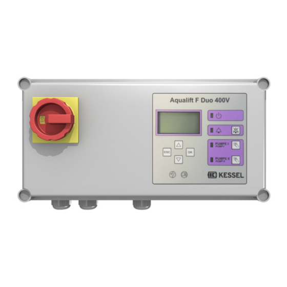
- Page 27 Main switch Cable passages, connections Display and control panel Screws for housing cover Type plate 010-532 Installation and operating manual 27 / 136...
-
Page 28: Technical Data
Technical data Maximum power (kW) at the 1.5 kW 4.3 kW 6.9 KW switch output (if cos φ = 1) Nominal current range 2.5 - 4.0 A 4.0 - 6.3 A 6.3 - 10 A Weight 2.5 kg (3 kg Duo) Dimensions (LxWxD), mm 190 x 280 x 130 (190 x 380 x 130 Duo) Operating voltage... -
Page 29: Installation
Installation Follow the safety instructions, see "Safety", page 25. For an overview of the printed board connections, see "Connection dia- grams", page 35 . Installing the control unit WARNING Disconnect system from energy sources! Make sure that cables and electrical components are disconnected from the power supply during work. - Page 30 Connecting the pump(s) Before connecting the pump, check whether the motor protection switch of the control unit is suitable for the power con- sumption of the pump(s) (see type plate). If necessary, set the motor protection switch to the nominal current of the pump (see type plate of the pump). Pull the connection cable through the cable passage(s) and tighten in the same way as the mains cable gland.
- Page 31 Connect sensors and control A connection overview of the printed boards is given at the end of this chapter. 4.5.1 Sensors without ATEX requirement Pressure sensor If a pressure sensor is to be used to detect the filling level it has to be connected as follows.
- Page 32 Connect the cable ends of the level sensor to the terminals (see "Fig. 3: Connecting the level sensor"). The connection Mono of level sensors is identical for both Mono and Duo systems. Use KESSEL junction box (art. no. 28799) to lengthen the connection cable of the level sensor. rt/RD rt/RD...
- Page 33 Red (plus) Fig. 8: Pegelsonde ATEX Black (minus) Yellow-green (equipotential bonding) Use KESSEL junction box (art. no. 28799) to lengthen the connection cable of the level sensor. 010-532 Installation and operating manual 33 / 136...
- Page 34 To ensure that the USB connection on the printed board can be accessed without opening the housing, a USB housing socket with cable and connector for installation in the housing of the control unit can be ordered from KESSEL (art. no.
- Page 35 Connection diagrams Aqualift Comfort Mono BATTERY KOMP+ KOMP- SICHERUNG Fusible 230VAC 50Hz POTENTIAL 315 mAT FREIER KONTAKT 4mm² 6mm² max: 42V 0,5A ATEX (optional) PEGELSONDE ALARM Alarm Alarme NETZ PUMPE Mains 363-242 400VAC 50Hz 400VAC 50Hz Aqualift Comfort Duo BATTERY bk rd KOMP+ KOMP-...
-
Page 36: Initial Commissioning
Initial commissioning Switch on and off Connect the battery Connect the battery connector(s) (2). Establish mains voltage (400V control units) Connect the mains cable to the mains power supply. Move main switch (1) into ON position. Initialisation starts automatically. The device checks the electrical components. Voltage test of the standby batteries. - Page 37 S1 / S3 operation ► Select the operating mode. The operating mode is noted in the technical data of the respective pump. |Maintenance interval| After the last entry, the menu appears. Maintenance interval ► Enter the maintenance interval specified in the standard. Initialisation is completed, control unit is ready.
-
Page 38: Troubleshooting
Troubleshooting |1.4.2 Next maintenance| The maintenance date for the system is set using the menu item. 38 / 136 Installation and operating manual 010-532... - Page 39 Display text Possible cause Remedial measure |Battery error| Battery is missing, is faulty or volt- Check battery charge state, correct age less than 13.5V. connection and damage to the battery connection terminals. |Maintenance date| (flash- Maintenance date is reached. Carry out maintenance. ing) No maintenance date entered.
- Page 40 Display text Possible cause Remedial measure |Max. run occur 1 Pump runs too frequently within a Check the system design, if neces- short time. sary, inform the customer service. |Communication error| Telecontrol modem error no network/credits, no connection to the modem, equipment fault |Alarm level| Level exceedance detected If it occurs frequently, check the...
-
Page 41: Overview Of Configuration Menu
Overview of configuration menu Overview menu The control menu is split into four menu areas: 0 System info - selected system, configured sensors, cur- rent measured values; if applicable, events or error mes- sages 1 Information - display of the operating data (e.g. voltage, - or float indicator current measured values, logbook or set parameters) 2 Maintenance - maintenance-relevant tasks (e.g. - Page 42 Automatic operation 2.1.1 Automatic operation On/Off Maintenance date 2.3.1 Last maintenance OK/Error 2.3.2 Next maintenance mm:hh - dd.mm.yy Maintenance done Maintenance interval 2.5.1 Commercial 3 months 2.5.2 Commercial 6 months 2.5.3 Private 12 months 2.5.4 Manual maintenance 2.5.5 no maintenance interval Calibration Settings Parameter...
- Page 43 3.6.6 F special lifting station 3.7.1 2.5 - 4A F special lifting station 3.7.2 4 - 6.3A F special lifting station 3.7.3 6.3 - 10A System configuration 3.5.2 Pumping station 3.6.1 Aqualift F XL 3.7.1 STZ1300 ATEX 3.7.2 STZ2500 ATEX 3.7.3 STZ3700 ATEX 3.7.4...
- Page 44 3.11. Reset 3.12 Expert mode 3.12.1 Power-up delay 0-99 PW: Ask customer service 3.12.2 Battery monitoring on/off 3.12.3 Battery threshold 0-18 3.12.4 Alternating operation on/off 3.12.5 Maximum operating cycles Data exchange Data read-out Update software Read in parameter 44 / 136 Einbau- und Betriebsanleitung 010-532_09...
- Page 45 Chère cliente, cher client, En qualité de producteur de pointe de produits novateurs dans le domaine de la technique d’assainissement, KESSEL pro- pose des réponses systématiques globales et un service orienté aux besoins de la clientèle. Nous misons simultanément sur les normes de qualité les plus élevées et une durabilité conséquente – non seulement lors de la fabrication de nos pro- duits, mais également pour leur utilisation à...
-
Page 46: Informations Spécifiques Aux Présentes Instructions
Informations spécifiques aux présentes instructions Les conventions de représentation suivantes facilitent l’orientation : Représentation Explication Numéro de repère 5 de la figure ci-contre Action de la figure Vérifier si la commande manuelle a été acti- Condition de réalisation de l’action vée. -
Page 47: Sécurité
Tous les travaux dépassant ce cadre sont réservés au domaine de compétence du service après-vente KESSEL ou d’un partenaire de service après-vente de KESSEL AG AVERTISSEMENT Pièces sous tension... - Page 48 Personne Activités autorisées sur les systèmes KESSEL Technicien spécialisé (connaît et com- Contrôle fonctionnel, confi- prend les instructions d’utilisation) guration du gestionnaire Électricien VDE 0105 (selon les Travaux sur l’ins- prescriptions de sécurité électrique tallation électrique ou les dispositions nationales) 1) L'utilisation et le montage sont réservés au domaine de compétence de personnes âgées de 18 ans révolus.
- Page 49 Interrupteur principal Passe-câbles, raccords Écran et panneau de commande Vis du couvercle du boîtier Plaque signalétique 010-532 Instructions de pose et d’utilisation 49 / 136...
-
Page 50: Caractéristiques Techniques
Caractéristiques techniques Puissance maximale(kW) à la sor- 1,5 KW 4,3 KW 6,9 KW tie de commutation (pour cos φ = 1) Plage de courant nominal 2,5 à 4,0 A 4,0 à 6,3 A 6,3 à 10 A Poids 2,5 kg (3 kg si Duo) Dimensions (LxlxH), mm 190 x 280 x 130 (190 x 380 x 130 si Duo) Tension de service... -
Page 51: Montage
Montage Respecter les consignes de sécurité, cf. "Sécurité", page 47. Aperçu des raccords de la platine, cf. "Schémas de raccorde- ment", page 57. Montage du gestionnaire AVERTISSEMENT Activer le système ! S'assurer que les conduites et composants électriques sont coupés de l'alimentation en tension pendant les travaux. - Page 52 Raccordement de la/des pompe(s) S’assurer, avant de raccorder la pompe, que le disjoncteur du moteur du gestionnaire est approprié à la puissance absor- bée par la/les pompe/s (voir la plaque signalétique). Au besoin, régler le disjoncteur du moteur sur le courant nominal de la pompe (voir la plaque signalétique de la pompe). Poser le câble de raccordement à...
- Page 53 Raccordement des capteurs et de la commande Un aperçu des raccords de la platine figure à la fin du présent document. 4.5.1 Capteurs sans requête ATEX Capteur de pression S’il est prévu d’utiliser un capteur de pression pour détermi- ner le niveau, procéder au raccordement comme indiqué ci- après.
- Page 54 (cf. "Fig. 3: Raccordement de la sonde de Mono niveau"). Le raccordement des sondes de niveau est iden- tique pour les systèmes Mono et Duo. Utiliser la boîte à bornes KESSEL (réf. 28799) pour ral- rt/RD rt/RD longer le câble de raccordement de la sonde de niveau.
- Page 55 Fig. 8: Pegelsonde ATEX Rouge (plus) Noire (moins) Jaune-vert (liai- son équipoten- tielle) Utiliser la boîte à bornes KESSEL (réf. 28799) pour ral- longer le câble de raccordement de la sonde de niveau. 010-532 Instructions de pose et d’utilisation 55 / 136...
- Page 56 Afin que le port USB situé sur la platine soit aussi accessible sans l'ouverture du boîtier, il est possible de commander un boîtier à douille USB, équipé d'un câble et d'un connecteur, à intégrer dans le boîtier du gestionnaire chez KESSEL (réf.
- Page 57 Schémas de raccordement Aqualift Comfort Mono BATTERY KOMP+ KOMP- SICHERUNG Fusible 230VAC 50Hz POTENTIAL 315 mAT FREIER KONTAKT 4mm² 6mm² max: 42V 0,5A ATEX (optional) PEGELSONDE ALARM Alarm Alarme NETZ PUMPE Mains 363-242 400VAC 50Hz 400VAC 50Hz Aqualift Comfort Duo BATTERY bk rd KOMP+...
-
Page 58: Première Mise En Service
Première mise en service Marche / arrêt Raccordement de la batterie Raccorder la/les fiches (2) de la/des batterie/s. Établissement de la tension de réseau (gestionnaires 400 volts) Raccorder le câble d'alimentation au secteur. Amener l’interrupteur principal (1) à la position <ON>. L’initialisation démarre automatiquement. - Page 59 |Fonctionnement S1 / S3| Menu s’affiche. Fonctionnement S1 / S3 ► Faire un choix entre les différents modes opérationnels. Le mode opérationnel figure aux caractéristiques techniques de la pompe s’y rapportant. |Intervalle de maintenance| Après la dernière saisie, l'écran affiche le menu Intervalle de maintenance ►...
-
Page 60: Aide En Cas De Panne
Aide en cas de panne |1.4.2 Prochaine maintenance| La date de maintenance pour le système est configurée dans l’option de menu 60 / 136 Instructions de pose et d’utilisation 010-532... - Page 61 Texte affiché Cause possible Remède |Erreur de la batterie| Batterie manque, est défectueuse Vérifier le chargement de la batterie, ou tension inférieure à 13,5 volts le raccordement correct et l’absence de dégradations des bornes de rac- cordement de la batterie. |Date de maintenance| La date de maintenance est Exécuter l'intervention de mainte-...
- Page 62 Texte affiché Cause possible Remède |Chute de pression| Défaut d'étanchéité du tuyau au Contrôler l'étanchéité du système du niveau du raccord à vis du tube sub- capteur de pression. mersible (ou de la cloche submer- sible) et/ou du gestionnaire. |Cycles de commutation Dépassement du nombre maximal Acquittement possible.
-
Page 63: Aperçu Du Menu De Configuration
Aperçu du menu de configuration Aperçu du menu Le menu de commande est divisé en quatre zones de menu : 0 Info système - Système sélectionné, capteurs configurés, valeurs actuelles mesurées, le cas échéant événements ou messages d’erreur - ou affichage de l’interrupteur à flotteur 1 Information - Affichage des données d’exploitation (par ex. - Page 64 1.6.14 Offset LEP 1.6.15 auto SDS 1.6.16 Fonctionnement S1/S3 0 à 99 Maintenance Mode automatique 2.1.1 Mode automatique MARCHE/ ARRÊT Date de maintenance 2.3.1 Maintenance précédente OK / Erreur 2.3.2 Maintenance suivante mm:hh - jj.mm.aa Maintenance effectuée Intervalle de maintenance 2.5.1 Commercial et industriel tous les 3 mois...
- Page 65 Aqualift F XL 300l 3.7.3 SPF4500 Aqualift F XL 300l 3.7.4 SPF5500 3.6.4 Aqualift F XL 450l 3.7.1 SPF3000 Aqualift F XL 450l 3.7.2 SPF4500 Aqualift F XL 450l 3.7.3 SPF5500 3.6.5 F XL installation sèche 3.7.1 SPF1500 F XL installation sèche 3.7.2 SPF300 3.6.6...
- Page 66 3.9.7 Texto cible 2 3.9.8 Texto cible 3 3.9.9 Statut 3.10. Langue 3.10.1 Deutsch 3.10.2 English 3.10.3 Français 3.10.4 Italiano 3.10.5 Nederlands 3.10.6 Polski 3.11. Remise à zéro 3.12 Mode expert 3.12.1 Temporisation de mise en cir- 0-99 cuit du réseau PW : demander au service 3.12.2 Surveillance de la batterie...
- Page 67 Cara cliente, caro cliente, in qualità di produttore premium di prodotti innovativi per la tecnica di drenaggio, KESSEL offre soluzioni di sistema integrate e un servizio orientato al cliente. Puntiamo sui massimi standard qualitativi e ci impegniamo coerentemente per la sosteni- bilità...
-
Page 68: Indicazioni Sulle Presenti Istruzioni
Indicazioni sulle presenti istruzioni Le seguenti convenzioni illustrative semplificano l’orientamento: Simbolo Spiegazione Posizione numero 5 della figura accanto Passaggio procedurale nella figura Controllare se il comando manuale è stato Presupposti per l’azione attivato. Premere OK. Passaggio procedurale L’impianto è pronto per funzionare. Risultato dell’azione vd. -
Page 69: Sicurezza
Tutti i lavori diversi da quelli elencati devono essere eseguiti esclusivamente dal servizio clienti KESSEL o da un partner di assistenza della KESSEL AG... - Page 70 Persona Mansioni ammesse sugli impianti KESSEL Elettricista specializzato VDE 0105 (nel Lavori all’instal- rispetto delle norme per la sicurezza elet- lazione elettrica trica o delle norme nazionali equivalenti) 1) Comando e montaggio possono essere affidati solo a persone che hanno compiuto il 18° anno di età.
- Page 71 Interruttore principale Passanti per i cavi, collegamenti Display e quadro di comando Viti per il coperchio dell’alloggiamento Targhetta 010-532_06 Istruzioni per l’installazione e l’uso 71 / 136...
-
Page 72: Dati Tecnici
Dati tecnici Potenza massima (kW) all’uscita 1,5 kW 4,3 kW 6,9 kW di commutazione (con cos φ = 1) Gamma di corrente nominale 2,5 - 4,0 A 4,0 - 6,3 A 6,3 - 10 A Peso 2,5 kg (3 kg Duo) Misure (Lu x La x Pr), mm 190 x 280 x 130 (190 x 380 x 130 Duo) Tensione di funzionamento... -
Page 73: Montaggio
Montaggio Rispettare le avvertenze di sicurezza, vd. "Sicurezza", pagina 69. Per una panoramica dei collegamenti sulla scheda, vd. "Schemi di collegamento", pagina 79 . Montaggio della centralina AVVERTENZA Disinserire l’impianto! Accertare che i cavi e i componenti elettrici siano separati dall’alimentazione di tensione durante i lavori. - Page 74 Collegamento della/e pompa/e Prima del collegamento della pompa, verificare se il salvamotore della centralina è adatto all’assorbimento di corrente della pompa/delle pompe (vedere la targhetta). Eventualmente impostare il salvamotore sulla corrente nominale della pompa (vedere la targhetta della pompa). Far passare il cavo di collegamento attraverso il pressacavo/i pressacavi e serrarlo analogamente al pressacavo del cavo di rete elettrica.
- Page 75 Collegamento della sensoristica e del comando Una visione d’insieme dei collegamenti della scheda si trova alla fine di questo capitolo. 4.5.1 Sensori senza requisito ATEX Sensore di pressione Se dovesse essere impiegato un sensore di pressione per la determinazione del livello di riempimento, questo andrà col- legato come segue.
- Page 76 è identico per gli impianti Mono e Duo. In caso di prolungamento del cavo di collegamento della rt/RD rt/RD sonda di livello, usare la scatola di derivazione KESSEL sw/BK sw/BK (codice articolo 28799). Colore filo...
- Page 77 Fig. 8: Pegelsonde ATEX Nero (meno) Giallo-verde (col- legamento equi- potenziale) In caso di prolungamento del cavo di collegamento della sonda di livello, usare la scatola di derivazione KESSEL (codice articolo 28799). 010-532_06 Istruzioni per l’installazione e l’uso 77 / 136...
- Page 78 Per fare in modo che il collegamento USB presente sul circuito stampato sia accessibile senza dover aprire l’alloggiamento è possibile ordinare presso KESSEL una presa USB per l’alloggiamento con cavo e connettore per l’installazione nell’allog- giamento della centralina (codice articolo 28785).
- Page 79 Schemi di collegamento Aqualift Comfort Mono BATTERY KOMP+ KOMP- SICHERUNG Fusible 230VAC 50Hz POTENTIAL 315 mAT FREIER KONTAKT 4mm² 6mm² max: 42V 0,5A ATEX (optional) PEGELSONDE ALARM Alarm Alarme NETZ PUMPE Mains 363-242 400VAC 50Hz 400VAC 50Hz Aqualift Comfort Duo BATTERY bk rd KOMP+...
-
Page 80: Prima Messa In Funzione
Prima messa in funzione Accensione e spegnimento Collegamento della batteria Collegare il connettore (2) della/e batteria/e. Generazione della tensione di rete elettrica (centraline da 400 V) Collegare il cavo di rete elettrica alla rete elettrica. Portare l’interruttore principale (1) in posizione ON. L’inizializzazione inizia autonomamente. - Page 81 Dimensioni delle prestazioni Selezione delle dimensioni delle prestazioni. La potenza della pompa è indicata sulla targhetta della pompa. |Funzionamento S1 / S3| Il menu viene visualizzato. Funzionamento S1 / S3 ► Selezione del tipo di funzionamento. Il tipo di funzionamento è indicato nei dati tecnici della rispettiva pompa. |Intervallo di manutenzione| Dopo l’ultima immissione comparirà...
-
Page 82: Aiuto In Caso Di Disturbi
Aiuto in caso di disturbi |1.4.2 Prossima manu- La scadenza di manutenzione per l’impianto può essere impostata tramite il punto del menu tenzione| 82 / 136 Istruzioni per l’installazione e l’uso 010-532_06... - Page 83 Testo visualizzato Possibile causa Rimedio |Errore della batteria| La batteria manca, è guasta o la ten- Controllare lo stato di carica della bat- sione è inferiore a 13,5 V. teria, il collegamento appropriato e la presenza di danni dei morsetti di col- legamento della batteria.
- Page 84 Testo visualizzato Possibile causa Rimedio |Cicli di commutazione Cicli di commutazione massimi Può essere confermato. Informare relè| superati. il servizio clienti. L’errore comparirà nuovamente dopo 1.000 cicli di com- mutazione ulteriori. |Tempo max. di funzio- La pompa funziona troppo a lungo Controllare il dimensionamento namento 1 ovvero...
-
Page 85: Visione D'insieme Del Menu Di Configurazione
Visione d’insieme del menu di configurazione Visione d’insieme del menu Il menù di comando è suddiviso in quattro aree: 0 Informazioni di sistema – impianto selezionato, sensori configurati, valori di lettura attuali, eventuali eventi o mes- saggi di errore 1 Informazioni – visualizzazione dei dati di funzionamento –... - Page 86 1.6.14 Offset LEP 1.6.15 SDS automatico 1.6.16 Funzionamento S1/S3 0 - 99 Manutenzione Funzionamento automatico 2.1.1 Funzionamento automatico ON/OFF Scadenza di manutenzione 2.3.1 Ultima manutenzione OK/Errore 2.3.2 Prossima manutenzione mm:hh - gg.mm.aa Manutenzione eseguita Intervallo di manutenzione 2.5.1 Commerciale 3 mesi 2.5.2 Commerciale 6 mesi 2.5.3...
- Page 87 Aqualift F XL 300l 3.7.4 SPF5500 3.6.4 Aqualift F XL 450l 3.7.1 SPF3000 Aqualift F XL 450l 3.7.2 SPF4500 Aqualift F XL 450l 3.7.3 SPF5500 3.6.5 F XL installazione a secco 3.7.1 SPF1500 F XL installazione a secco 3.7.2 SPF300 3.6.6 Stazione di sollevamento spe- 3.7.1...
- Page 88 3.9.5 Centrale SMS 3.9.6 Destinazione SMS 1 3.9.7 Destinazione SMS 2 3.9.8 Destinazione SMS 3 3.9.9 Stato 3.10. Lingua 3.10.1 Deutsch 3.10.2 English 3.10.3 Français 3.10.4 Italiano 3.10.5 Nederlands 3.10.6 Polski 3.11. Azzeramento 3.12 Modalità “Esperti” 3.12.1 Ritardo di accensione rete elet- 0-99 trica Password: da richiedere al...
- Page 89 Beste klant, Als premium fabrikant van innovatieve producten voor de afwateringstechniek biedt KESSEL totale systeemoplossingen en klantgerichte service. Wij stellen hierbij maximale kwaliteitsnormen en zetten consequent in op duurzaamheid, niet alleen bij de productie van onze producten, maar ook met het oog op hun langdurige gebruik zetten wij ons in voor een permanente bescherming van u en uw eigendom.
-
Page 90: Informatie Over Deze Handleiding
Informatie over deze handleiding De volgende weergaveconventies maken de oriëntatie eenvoudiger: Afbeelding Uitleg Positienummer 5 van nevenstaande afbeelding Handeling op de afbeelding … Controleren of de handbesturing is inge- Voorwaarde voor de handeling schakeld. Op OK drukken. Werkstap De installatie is bedrijfsklaar. Resultaat van de handeling zie "Veiligheid", pagina 91 Kruisverwijzing naar hoofdstuk 2... -
Page 91: Veiligheid
Alle verdergaande werkzaamheden mogen enkel door de KESSEL klantenservice of een servicepartner van KESSEL AG worden uitgevoerd WAARSCHUWING Spanningvoerende delen Bij werkzaamheden aan de elektrische bekabeling en aansluitingen het onderstaande in acht nemen. - Page 92 Persoon Vrijgegeven werkzaamheden bij KESSEL-installaties Deskundige (kent, begrijpt gebruiksaanwijzing) Functiecontrole, configura- tie van de besturingskast Elektricien VDE 0105 (volgens voorschriften Werkzaamheden aan voor elektr. veiligheid of nationaal equivalent) de elektrische installatie 1) Bediening en montage mogen alleen door personen van 18 jaar of ouder worden uitgevoerd.
- Page 93 Hoofdschakelaar Kabeldoorvoeren, aansluitingen Display en besturingspaneel Schroeven voor deksel van behuizing Typeplaatje 010-532 Inbouw- en montagehandleiding 93 / 136...
-
Page 94: Technische Gegevens
Technische gegevens Maximaal vermogen (kW) bij uit- 1,5 KW 4,3 KW 6,9 KW gang schakelaar (bij cos. φ = 1) Nominaal stroombereik 2,5 – 4,0 A 4,0 – 6,3 A 6,3 – 10 A Gewicht 2,5 kg (3 kg Duo) Afmetingen (lxbxd), mm 190 x 280 x 130 (190 x 380 x 130 Duo) Bedrijfsspanning... -
Page 95: Monteren
Monteren Veiligheidsinstructies in acht nemen, zie "Veiligheid", pagina 91. Zie voor een overzicht van de printplaataansluitingen zie "Aansluitschema’s", pagina 101. Besturingskast monteren WAARSCHUWING Installatie loskoppelen! Waarborgen dat leidingen en elektrische componenten tijdens de werkzaamheden losge- koppeld zijn van de voedingsspanning. De besturingskast kan uitsluitend worden geopend als de hoofdschakelaar zich in stand OFF bevindt. - Page 96 Pomp(en) aansluiten Voordat de pomp wordt aangesloten controleren of de motorbeveiligingsschakelaar van de besturingskast geschikt is voor het stroomverbruik van de pomp(en) (zie typeplaatje). Eventueel motorbeveiligingsschakelaar instellen op de nominale stroomsterkte van de pomp (zie typeplaatje van de pomp). Aansluitkabels door de kabeldoorvoer(en) trekken en analoog aan de kabelschroefverbinding van de elektriciteitsleiding vastdraaien.
- Page 97 Sensoren en besturing aansluiten Aan het einde van dit document vindt u een aansluitoverzicht van de printplaat. 4.5.1 Sensoren zonder ATEX-eisen Druksensor Als een druksensor moet worden gebruikt om het vulpeil vast te stellen, deze als volgt aansluiten. Luchtslang met behulp van een trekveer door de mantel- buis voeren en hierbij de slang met de afdekkap aan de trekveer bevestigen.
- Page 98 "Afb. 3: Peilsonde aansluiten") aansluiten. Peilsondes wor- Mono den bij Mono- en Duo-installaties op dezelfde manier aange- sloten. Bij het verlengen van de aansluitkabel van de peilsonde rt/RD rt/RD KESSEL-aansluitdoos (art.nr. 28799) gebruiken. sw/BK sw/BK Kleur aders Ben. op print- Kleur klemmen plaat...
- Page 99 Benaming Van vlotterscha- rt/RD kelaar naar peils- onde ombouwen Afb. 8: Pegelsonde ATEX rood (plus) zwart (min) Geel-groen (aar- ding) Bij het verlengen van de aansluitkabel van de peilsonde KESSEL-aansluitdoos (art.nr. 28799) gebruiken. 010-532 Inbouw- en montagehandleiding 99 / 136...
- Page 100 USB-aansluiting naar buiten voeren Om toegang te krijgen tot de op de printplaat aanwezige USB-aansluiting zonder de behuizing te openen, kan bij KESSEL een USB-behuizingsbus met kabel en stekker voor inbouw in de behuizing van de besturingskast (zie art.nr. 28785) worden besteld.
- Page 101 Aansluitschema’s Aqualift Comfort Mono BATTERY KOMP+ KOMP- SICHERUNG Fusible 230VAC 50Hz POTENTIAL 315 mAT FREIER KONTAKT 4mm² 6mm² max: 42V 0,5A ATEX (optional) PEGELSONDE ALARM Alarm Alarme NETZ PUMPE Mains 363-242 400VAC 50Hz 400VAC 50Hz Aqualift Comfort Duo BATTERY bk rd KOMP+ KOMP- SICHERUNG...
-
Page 102: Eerste Inbedrijfstelling
Eerste inbedrijfstelling In- en uitschakelen Batterij aansluiten Stekker (2) van de batterij(en) aansluiten. Netspanning tot stand brengen (400V-besturingskasten) Elektriciteitsleiding op stroomnet aansluiten. Hoofdschakelaar (1) in stand ON zetten. Initialisatie start automatisch. Apparaat controleert elektrische componenten. spanningscontrole van de noodstroombatterijen. |3.10. Taal| Menupunt wordt aangegeven. - Page 103 S1 / S3 bedrijf ► De bedrijfsmodus kiezen. De bedrijfsmodus is opgenomen in de technische gegevens van de desbetreffende pomp. |Onderhoudsinterval| Na de laatste invoer verschijnt het menu Onderhoudsinterval ► Invoer van de normatief gespecificeerde onderhoudsinterval. Initialisatie afgesloten, besturingskast is bedrijfsklaar. Bedieningsmodus activeren Op de toets OK op het besturingspaneel drukken.
-
Page 104: Hulp Bij Storingen
Hulp bij storingen |1.4.2 Volgende onderhoud| De onderhoudsdatum voor de installatie wordt via het menupunt ingesteld. 104 / 136 Inbouw- en montagehandleiding 010-532... - Page 105 Tekst op display Mogelijke oorzaak Remedie |Accufout| Accu ontbreekt, is defect of voltage Accu op laadstatus, vakkundige aan- lager dan 13,5 V. sluiting en beschadiging van de aan- sluitklemmen van de accu controle- ren. |Onderhoudsdatum| (knip- Onderhoudsdatum is bereikt. Onderhoud uitvoeren. pert) Geen onderhoudsdatum opgege- Onderhoudsdatum opgeven.
- Page 106 Tekst op display Mogelijke oorzaak Remedie |Limiet looptijd 1 resp. Pomp is tijdens pompcyclus te lang Ontwerp installatie controleren, evt. ingeschakeld. klantenservice informeren. |Limiet loopfrequentie Pomp draait te vaak in korte tijd. Ontwerp installatie controleren, evt. resp. klantenservice informeren. |Communicatiestoring| Fout in de modem voor afstandsbe- geen netwerk/tegoed, geen verbin- sturing...
-
Page 107: Overzicht Configuratiemenu
Overzicht configuratiemenu Overzicht van het menu Het besturingsmenu is ingedeeld in vier delen: 0 Systeeminfo: geselecteerde installatie, geconfigureerde sensoren, actuele meetwaarden, eventuele foutmeldingen 1 Informatie: weergave van bedrijfsinformatie (bijv. bedrijfsspanning, actuele meetwaarden, logboek of inge- – resp. vlotteroverzicht stelde parameters) 2 Onderhoud: onderhoudsinformatie (bijv. - Page 108 Onderhoudsdatum 2.3.1 Laatste onderhoud OK/fout 2.3.2 Volgende onderhoud mm:hh – dd.mm.yy Onderhoud uitgevoerd Onderhoudsinterval 2.5.1 Bedrijfsmatig 3 maanden 2.5.2 Bedrijfsmatig 6 maanden 2.5.3 Particulier 12 maanden 2.5.4 Handmatig onderhoud 2.5.5 Geen onderhoudsinterval Kalibratie Instellingen Parameters 3.1.1 Sensorhoogte 0 – 999 3.1.2 Inschakelblokkering 0 –...
- Page 109 F speciale opvoerinstallatie 3.7.2 4 – 6,3 A F speciale opvoerinstallatie 3.7.3 6,3 – 10 A Installatieconfiguratie 3.5.2 Pompstation 3.6.1 Aqualift F XL 3.7.1 STZ1300 ATEX 3.7.2 STZ2500 ATEX 3.7.3 STZ3700 ATEX 3.7.4 TPF 1kw3 ATEX 3.7.5 TPF 1kw9 ATEX 3.7.6 AP501 3.7.7...
- Page 110 3.12 Expertmodus 3.12.1 Inschakelvertraging net 0 – 99 PW: bij klantenservice opvra- 3.12.2 Accucontrole aan/uit 3.12.3 Drempel accu 0 –18 3.12.4 Alternerend bedrijf aan/uit 3.12.5 Maximale schakelcycli Gegevensoverdracht Gegevens uitlezen Software updaten Parameters inlezen 110 / 136 Einbau- und Betriebsanleitung 010-532_09...
- Page 111 Szanowna Klientko, Szanowny Kliencie, jako producent najwyższej klasy innowacyjnych produktów z zakresu techniki odwadniania firma KESSEL oferuje komplek- sowe rozwiązania systemowe i serwis odpowiadający potrzebom klientów. Stawiamy sobie najwyższe standardy jakościowe i konsekwentnie stawiamy na trwałość – nie tylko podczas produkcji naszych urządzeń, lecz również w zakresie ich długo- trwałego użytkowania dbamy o to, by stale gwarantowane było bezpieczeństwo użytkownika i jego mienia.
-
Page 112: Wskazówki Dotyczące Niniejszej Instrukcji
Wskazówki dotyczące niniejszej instrukcji Poniższe formy oznaczeń ułatwiają orientację: Oznaczenie Objaśnienie Numer pozycji 5 na rysunku obok Krok postępowania na rysunku Sprawdzić, czy aktywowane zostało stero- Warunek postępowania wanie ręczne. Nacisnąć przycisk OK. Krok postępowania Urządzenie jest gotowe do pracy. Wynik postępowania patrz "Bezpieczeństwo", strona 113 Odniesienie do rozdz. -
Page 113: Bezpieczeństwo
Wszelkie inne prace może wykonywać wyłącznie serwis klienta KESSEL lub partner serwisowy firmy KESSEL AG. OSTRZEŹENIE Elementy będące pod napięciem Podczas prac przy przewodach i przyłączach elektrycznych należy przestrzegać następujących wskazówek. - Page 114 Osoba Dozwolone czynności przy urządzeniach KESSEL Wykwalifikowany elektryk wg VDE 0105 (zgod- Prace przy insta- nie z przepisami bezpieczeństwa elektrycz- lacji elektrycznej nego lub ich krajowymi odpowiednikami) 1) Obsługi i montażu mogą dokonywać wyłącznie osoby, które ukończyły 18 rok życia.
- Page 115 Wyłącznik główny Przepusty kablowe, przyłącza Wyświetlacz i pole obsługi Śruby do pokrywy obudowy Tabliczka znamionowa 010-532 Instrukcja zabudowy i obsługi 115 / 136...
-
Page 116: Dane Techniczne
Dane techniczne Maksymalna moc (kW) na wyj- 1,5 kW 4,3 kW 6,9 kW ściu przełączającym (dla cos φ = 1) Zakres prądu znamionowego 2,5 - 4,0 A 4,0 - 6,3 A 6,3 - 10 A Ciężar 2,5 kg (Duo 3 kg) Wymiary (dł... -
Page 117: Montaż
Montaż Przestrzegać zasad bezpieczeństwa, patrz patrz "Bezpieczeństwo", strona 113. Przegląd przyłączy na płytce drukowanej patrz patrz "Schematy połączeń", strona 123 . Montaż urządzenia sterującego OSTRZEŹENIE Odłączyć urządzenie od prądu! Upewnić się, że przewody i komponenty elektryczne są na czas prac odłączone od zasilania napięciem. - Page 118 Podłączenie pomp(y) Przed podłączeniem pompy sprawdzić, czy stycznik silnikowy urządzenia sterującego jest przystosowany do poboru prądu pomp(y) (patrz tabliczka znamionowa). Ewentualnie ustawić stycznik silnikowy na prąd znamionowy pompy (patrz tabliczka znamionowa pompy). Poprowadzić kabel przyłączeniowy przez przepust(y) w urządzeniu i podłączyć w ten sam sposób jak dławik kablowy przewodu sieciowego.
- Page 119 Podłączenie czujników i sterowania Przegląd przyłączy na płytce drukowanej znajduje się na końcu tego rozdziału. 4.5.1 Czujniki bez ATEX Czujnik ciśnienia Jeżeli do pomiaru stanu napełnienia używany ma być czuj- nik ciśnienia, należy go podłączyć w następujący sposób. Przymocować koniec przewodu giętkiego ciśnieniowego z nakładką...
- Page 120 Rys. 3: Podłączenie sondy hydrostatycznej czarny WŁ./WŁ.1 niebieski Do przedłużenia przewodu przyłączeniowego sondy hydrostatycznej należy użyć puszki rozgałęźnej KESSEL (nr art. 28799). 4.5.1.2 Podłączenie membranowego czujnika ciśnienia Membranowy czujnik ciśnienia w urządzeniach typu Mono Podłączyć zakończenia kabli membranowego czujnika ciśnienia do zacisków (patrz "rys. 4: Membranowy czujnik Mono ciśnienia Mono").
- Page 121 Rys. 8: Pegelsonde ATEX tyczną Czerwony (+) Czarny (-) Żółto-zielony (wyrównanie potencjałów) Do przedłużenia przewodu przyłączeniowego elektro- dowej sondy poziomu należy użyć puszki rozgałęźnej KESSEL (nr art. 28799). 010-532 Instrukcja zabudowy i obsługi 121 / 136...
- Page 122 Zamontować modem TeleControl (nr art. 28792) według odpowiedniej instrukcji montażu 434-033. Wyprowadzenie portu USB Jeżeli port USB ma być dostępny bez konieczności otwarcia obudowy, można zamówić w firmie KESSEL gniazdo USB z kablem i wtyczką do zabudowy w obudowie urządzenia sterującego (nr art. 28785).
- Page 123 Schematy połączeń Aqualift Comfort Mono BATTERY KOMP+ KOMP- SICHERUNG Fusible 230VAC 50Hz POTENTIAL 315 mAT FREIER KONTAKT 4mm² 6mm² max: 42V 0,5A ATEX (optional) PEGELSONDE ALARM Alarm Alarme NETZ PUMPE Mains 363-242 400VAC 50Hz 400VAC 50Hz Aqualift Comfort Duo BATTERY bk rd KOMP+ KOMP-...
-
Page 124: Pierwsze Uruchomienie
Pierwsze uruchomienie Włączenie i wyłączenie Podłączenie baterii Podłączyć wtyczkę (2) baterii. Utworzenie napięcia sieciowego (urządzenia sterujące 400 Podłączyć przewód sieciowy do prądu. Ustawić wyłącznik główny (1) w pozycji ON. Inicjalizacja rozpoczyna się samoistnie. Urządzenie sprawdza podzespoły elektryczne. Dokonywana jest kontrola napięcia baterii do zasilania awaryjnego. - Page 125 |Tryb S1/S3| Wyświetla się menu Tryb S1/S3 ► Wybrać tryb. Rodzaj trybu jest podany w danych technicznych danej pompy. |Częstotliwość konserwacji| Po wprowadzeniu ostatniej danej wyświetla się menu Częstotliwość konserwacji ► Podać zadaną normą częstotliwość konserwacji. Inicjalizacja jest zakończona, urządzenie sterujące jest gotowe do pracy. Aktywacja trybu obsługi |0 Informacja o Nacisnąć...
-
Page 126: Pomoc W Razie Usterek
Pomoc w razie usterek ||1.4.2 Następna konserwacja| Termin konserwacji urządzenia ustawia się w punkcie menu 126 / 136 Instrukcja zabudowy i obsługi 010-532... - Page 127 Tekst wskazania Kon- Możliwa przyczyna Rozwiązanie takt bez- poten- cja- łowy |Błąd baterii| Brak baterii, uszkodzona bateria lub Sprawdzić stan naładowania baterii, napięcie niższe niż 13,5 V. sprawdzić prawidłowe podłączenie i uszkodzenie zacisków przyłączenio- wych baterii. |Termin konserwacji| Nadszedł termin konserwacji. Wykonać...
- Page 128 Tekst wskazania Kon- Możliwa przyczyna Rozwiązanie takt bez- poten- cja- łowy |Ochrona silnika 1 lub Zadziałał wyłącznik samoczynny Ustawić wartość prądu odpowied- silnikowy – wyłącznik samoczynny nio do pompy. silnikowy jest nieprawidłowo usta- Usunąć blokadę. wiony. Wymienić pompę, jeśli jest uszko- Za wysoki prąd pompy wskutek dzona.
-
Page 129: Przegląd Menu Konfiguracyjnego
Przegląd menu konfiguracyjnego Przegląd menu Menu sterowania jest podzielone na cztery obszary menu: 0 Informacja o systemie – wybrane urządzenie, skonfigu- rowane czujniki, aktualne wartości pomiarowe, ewentualnie wydarzenia lub komunikaty o błędach 1 Informacja – dane eksploatacyjne (np. napięcie robocze, - lub wyświetlenie przełącznika pływakowego aktualne wartości zmierzone, dziennik zdarzeń... - Page 130 1.6.16 Tryb S1/S3 0 - 99 Konserwacja Tryb automatyczny 2.1.1 Tryb automatyczny WŁ./WYŁ. Termin konserwacji 2.3.1 Ostatnia konserwacja OK/błąd 2.3.2 Następna konserwacja mm:hh - dd.mm.rr Konserwacja wykonana Częstotliwość konserwacji 2.5.1 Do użytku komercyjnego – 3 miesiące 2.5.2 Do użytku komercyjnego – 6 miesięcy 2.5.3 Do użytku prywatnego –...
- Page 131 3.6.4 Aqualift F XL 450 l 3.7.1 SPF3000 Aqualift F XL 450 l 3.7.2 SPF4500 Aqualift F XL 450 l 3.7.3 SPF5500 3.6.5 F XL ustawienie suche 3.7.1 SPF1500 F XL ustawienie suche 3.7.2 SPF300 3.6.6 F Przepompownia specjalna 3.7.1 2,5 - 4 A F Przepompownia specjalna 3.7.2...
- Page 132 3.9.9 Stan 3.10. Język 3.10.1 Deutsch 3.10.2 English 3.10.3 Français 3.10.4 Italiano 3.10.5 Nederlands 3.10.6 Polski 3.11. Resetowanie 3.12 Tryb eksperta 3.12.1 Opóźnienie włączenia sieci 0 - 99 PW: zasięgnąć informacji w 3.12.2 Nadzór baterii WŁ./WYŁ. serwisie klienta 3.12.3 Próg baterii 0 - 18 3.12.4 Tryb naprzemienny...
- Page 134 134 / 136 010-532_09...
- Page 135 010-532_09 135 / 136...
- Page 136 Registrieren Sie Ihr Produkt online, um von einer schnelleren Hilfe zu profitieren! http://www.kessel.de/service/produktregistrierung.html KESSEL AG, Bahnhofstr. 31, 85101 Lenting, Deutschland...
Need help?
Do you have a question about the Aqualift F Mono 400V and is the answer not in the manual?
Questions and answers