Kessel GTF1000 Manual
Hide thumbs
Also See for GTF1000:
- Installation, operation and maintenance manual (30 pages) ,
- Installation, operation and maintenance manual (24 pages) ,
- Installation and operating instructions manual (80 pages)
Table of Contents
Advertisement
Available languages
Available languages
Quick Links
2020/09
Tauchpumpe
Tauchpumpe
Tauchpumpe
GTF1000/GTF1200/
GTF1000/GTF1200/
GTF1000/GTF1200/
GTF1250
GTF1250
GTF1250
Einbau- und Betriebsanleitung
Einbau- und Betriebsanleitung
Einbau- und Betriebsanleitung
DE
.......................................................................... 2
EN
........................................................................ 14
FR
........................................................................ 26
IT
........................................................................ 38
NL
........................................................................ 50
PL
........................................................................ 62
016-212_01
Advertisement
Chapters
Table of Contents

Subscribe to Our Youtube Channel
Related Manuals for Kessel GTF1000


Summary of Contents for Kessel GTF1000
- Page 1 Tauchpumpe Tauchpumpe Tauchpumpe GTF1000/GTF1200/ GTF1000/GTF1200/ GTF1000/GTF1200/ GTF1250 GTF1250 GTF1250 Einbau- und Betriebsanleitung Einbau- und Betriebsanleitung Einbau- und Betriebsanleitung ................2 ................ 14 ................ 26 ................ 38 ................ 50 ................ 62 2020/09 016-212_01...
-
Page 2: Table Of Contents
Inhalt Liebe Kundin, lieber Kunde, als Premiumhersteller von innovativen Produkten für die Hinweise zu dieser Anleitung........Entwässerungstechnik bietet KESSEL ganzheitliche Sys- Sicherheit..............temlösungen und kundenorientierten Service. Dabei stel- Technische Daten............ len wir höchste Qualitätsstandards und setzen konsequent auf Nachhaltigkeit - nicht nur bei der Herstellung unserer Montage.............. -
Page 3: Hinweise Zu Dieser Anleitung
Folgende Symbole werden verwendet: Hinweise zu dieser Anleitung Zeichen Bedeutung Folgende Darstellungskonventionen erleichtern die Ori- entierung: Gerät freischalten! Darstellung Erläuterung siehe Abbildung 1 Gebrauchsanweisung beachten Positionsnummer 5 von nebenstehender Abbildung CE-Kennzeichnung Handlungsschritt in Abbildung Prüfen, ob Hand- Warnung Elektrizität steuerung aktiviert Handlungsvoraussetzung wurde. -
Page 4: Sicherheit
ACHTUNG Sicherheit Anlage freischalten! Sicherstellen, dass die elektrischen Komponen- Allgemeine Sicherheitshinweise ten während der Arbeiten von der Spannungsver- sorgung getrennt sind. WARNUNG Diese Pumpe enthält elektrische Spannungen und steuert drehende, mechanische Pumpenteile. Bei Nichtbeachtung der Bedienungsanleitung können erheblicher Sachschaden, Körperverletzung oder gar tödliche Unfälle die Folge sein. - Page 5 Die Variante Resistant ist überdies geeignet für eine Kom- Bestimmungsgemäße Verwendung bination aus Abwässern und salzhaltigen Medien sowie für Die KESSEL-Tauchpumpen sind zum Abpumpen von fäka- Kondensat aus Brennwertgeräten. lienfreiem Abwasser im häuslichen Bereich vorgesehen. Das Wasser kann durch Schwebstoffe oder kleinere Gegen- stände verunreinigt sein.
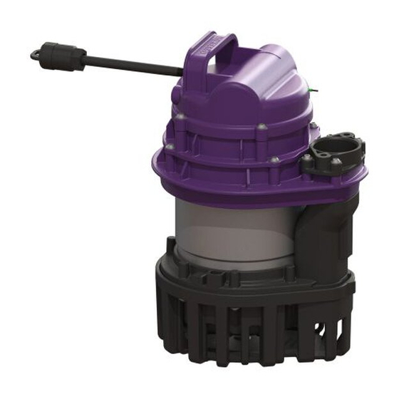
- Page 6 Der Stützfuß der GTF 1200 und GTF 1250 erlaubt einen freien Kugeldurchgang von 30mm. PosNr. Bauguppen und Funktionen Ansaugkorb Spiralgehäuse Freistromrad Netzstecker Schwimmerschalter Druckanschluss Position für Entlüftungsöffnung Schlauchadapter 1 1/4", 1 1/2" (nur GTF1000) Stützfuß (nur GTF1200, GTF 1250) 6 / 76 016-212_01...
-
Page 7: Technische Daten
Technische Daten Angabe / Pumpenart GTF1000 GTF1200, 1250 Gewicht 10 kg 10 kg 1,4 kW / 0,84 kW, Leistung P1 / P2 1,3 kW / 0,75 kW 1,3kW / 10,8 kW Drehzahl 2800 min-1 2.650 min-1 Betriebsspannung 230 V; 50 Hz 230 V;... - Page 8 Angabe / Pumpenart GTF1000 GTF1200, 1250 Betriebsart S3 - 50 % S3 - 50 % Pumpe bei mobilem Einsatz (als Tauchpumpe mit Schwimmerschalter) 1000 Einschaltniveau [mm] Ausschaltniveau [mm] 8 / 76 016-212_01...
-
Page 9: Montage
Montage Gerät nicht am Kabel ziehen oder tragen! Pumpe am Tragegriff anfassen und tragen. Druckanschluss herstellen (A - Einsatz als System- pumpe/Austauschpumpe) Pumpe platzieren. Einhandverschluss arretieren. Schlauchanschluss montieren (B - mobiler Einsatz) Anschlussstutzen demontieren (zwei Schrauben). Adapter für Schlauchanschluss montieren. Pumpe auf ebener Fläche stabil positionieren. - Page 10 Stecker einstecken. Abwasserpumpe läuft selbsttätig an (bei entsprechendem Niveau). Prüfen, ob Druckleitung nach erstem Laufen der Pumpe noch fest angeschlossen ist. Funktionsprüfung (siehe "Wartung", Seite 11) durch- führen. 10 / 76 016-212_01...
-
Page 11: Wartung
Wartung Wartungsintervall Funktionsprüfung Die Wartung muss gemäß Normvorgabe in folgenden Zeit- Netzanschluss herstellen. abständen erfolgen: Schwimmerschalter anheben oder Pumpe per Taste 1/4-jährlich bei Anlagen in Gewerbebetrieben Handbetrieb am Schaltgerät aktivieren. 1/2-jährlich bei Anlagen in Mehrfamilienhäusern Pumpe läuft selbsttätig an. jährlich bei Anlagen in Einfamilienhäusern Prüfen, ob gleichmäßige Laufgeräusche zu hören sind und die Pumpe unterbrechungsfrei läuft. - Page 12 Wartungstätigkeiten ACHTUNG Anlage freischalten! Sicherstellen, dass die elektrischen Komponen- ten während der Arbeiten von der Spannungs- versorgung getrennt sind. Freigängigkeit des Schwimmerschalters sicherstellen. Bewegliche Komponenten demontieren Ansaugkorb demontieren. Spiralgehäuse demontieren. Freistromrad auf Leichtläufigkeit überprüfen, ggf. demon- tieren. Reinigung durchführen Entlüftungsöffnung freimachen. Demontierte Komponenten mittels Wasserbad reinigen.
- Page 13 Hilfe bei Störungen Fehler Ursache Abhilfemaßnahmen Keine Netzspannung vorhanden Netzspannung prüfen Hausstrom-Sicherung hat ausgelöst Sicherung wieder einschalten Anschlussleitung beschädigt Reparatur durch Elektrofachkräfte/Servicepart- Pumpe läuft nicht Schwimmerschalter defekt Kundendienst kontaktieren Überhitzung Tauchpumpe schaltet sich nach Temperatur- rückgang selbsttätig wieder ein Verunreinigungen, Feststoffe haben sich zwi- Pumpe reinigen Freistromrad blockiert schen Freistromrad und Spiralgehäuse festge-...
- Page 14 Contents Dear customer, As a premium manufacturer of innovative products for drain- Notes on this manual..........ing technology, KESSEL offers integrated system solutions Safety............... and customer-oriented service. In doing so, we set the high- Technical data............est quality standards and focus firmly on sustainability - not only with the manufacturing of our products, but also with Installation..............
-
Page 15: Notes On This Manual
The following symbols are used: Notes on this manual Icon Meaning The following conventions make it easier to navigate the manual: Isolate device! Symbol Explanation See Figure 1 Observe the instructions for use Position number 5 from the adjacent figure Action step in figure CE marking Check whether... -
Page 16: Safety
NOTICE Safety Disconnect system from energy sources! Ensure that the electrical components are discon- General safety notes nected from the electrical power supply during the work. WARNING This pump contains electric charges and controls rotating mechanical system components. Non-com- pliance with the operating instructions may result in considerable damage to property, personal injuries or even fatal accidents. - Page 17 Pumping off smaller water bodies or accumulation of Intended use water (mobile use) The KESSEL submersible pumps are designed for pumping as a system pump for lifting stations (GTF 1000) and out faecal-free wastewater in households. The water can be pumping stations (GTF1200, GTF1250) in the Aqualift soiled by suspended solids or smaller objects.
- Page 18 30mm. Item no. Assemblies and functions Intake cage Spiral housing Multi-vane impeller Mains plug Float switch Pressure pipe connection Position for vent Hose adapter 1 1/4", 1 1/2" (GTF1000 only) Stand (GTF1200, GTF 1250 only) 18 / 76 016-212_01...
-
Page 19: Technical Data
Technical data Information / pump type GTF1000 GTF1200, 1250 Weight 10 kg 10 kg 1.4 kW / 0.84 kW, Power P1 / P2 1.3 kW / 0.75 kW 1.3kW / 10.8 kW Speed 2800 rpm 2650 rpm Operating voltage 230 V; 50 Hz 230 V;... - Page 20 Information / pump type GTF1000 GTF1200, 1250 Operating mode S3 - 50 % S3 - 50 % Pump for mobile use (as sub- mersible pump with float switch) 1000 Switch-on level [mm] Switch-off level [mm] 20 / 76 016-212_01...
-
Page 21: Installation
Installation Do not pull or carry the device by the cable! Hold and carry the pump by the carrying handle. Connecting the pressure pipe (A - use as system pump/ replacement pump) Position the pump. Lock the one-handed closure. Fitting the hose connection (B - mobile use) Remove the connecting socket (two screws). - Page 22 Plug in the plug. The wastewater pump starts up automatically (at corre- sponding level). Check whether the pressure pipe is still firmly connected after the pump has started running. Carry out a functional test (see "Maintenance", page 23). 22 / 76 016-212_01...
-
Page 23: Maintenance
Maintenance Maintenance interval Functional test According to standard specifications, maintenance must be Connect to the mains connection. carried out at the following intervals: Lift the flow switch or activate the pump using the manual 1/4-yearly for systems in commercial operations operation button at the control unit. - Page 24 Maintenance activities NOTICE Disconnect system from energy sources! Ensure that the electrical components are dis- connected from the electrical power supply dur- ing the work. Ensure the float switch can move freely. Dismantle the movable components Remove the intake cage. Remove the spiral housing.
- Page 25 Troubleshooting Error Cause Remedial measures No mains voltage available Check the mains voltage Mains power fuse has tripped Switch fuse on again Connection cable is damaged Repair only by qualified electricians/service partners Pump is not running Float switch is defective Contact customer service Overheating Submersible pump switches back on again...
- Page 26 Sommaire Chère cliente, cher client, En qualité de producteur de pointe de produits novateurs Informations spécifiques aux présentes instruc- dans le domaine de la technique d’assainissement, KESSEL tions................. propose des réponses systématiques globales et un ser- Sécurité..............vice orienté aux besoins de la clientèle. Nous misons simul- Caractéristiques techniques........
-
Page 27: Informations Spécifiques Aux Présentes Instruc
Les instructions emploient les pictogrammes suivants : Informations spécifiques aux Picto- présentes instructions gramme / Signification label Les conventions de représentation suivantes facilitent l’orientation : Activer l’appareil ! Représentation Explication voir figure 1 Observer le mode d'emploi Numéro de repère 5 de la figure ci-contre Action de la figure Label de conformité... -
Page 28: Sécurité
AVIS Sécurité Activer le système ! S'assurer que l'alimentation électrique est cou- Consignes de sécurité générales pée pendant les travaux. AVERTISSEMENT Cette pompe est sujette à des tensions électriques et commande des éléments mécaniques en rotation. L'inobservation des instructions de service risque de provoquer des dommages matériels considé- rables, des blessures, voire des accidents mortels. - Page 29 Pompage de petits plans d'eau ou d'accumulations d'eau Utilisation conforme à l'usage prévu (utilisation mobile) Les pompes submersibles KESSEL servent au refoulement En tant que pompe pour postes de relevage (GTF 1000) des eaux usées sans matières fécales domestiques. L’eau et stations de relevage (GTF1200, GTF1250) de la série...
- Page 30 à bille libre de 30 mm. PosNr. Sous-groupes et fonctions Grille d’aspiration Volute de pompe Roue vortex Fiche de secteur Interrupteur à flotteur Refoulement Position d'ouverture d'aération Adaptateur de tuyau 1 1/4", 1 1/2" (GTF1000 uniquement) 30 / 76 016-212_01...
-
Page 31: Caractéristiques Techniques
Caractéristiques techniques Indication / type de pompe GTF 1000 GTF1200, 1250 Poids 10 kg 10 kg 1,4 kW / 0,84 kW, Puissance P1 / P2 1,3 kW / 0,75 kW 1,3kW / 10,8 kW Régime 2800 min-1 2 650 min-1 Tension de service 230 volts ;... - Page 32 Indication / type de pompe GTF 1000 GTF1200, 1250 Mode de fonctionnement S3 - 50 % S3 - 50 % Pompe à usage mobile (en tant que pompe GTF 1000 submersible avec interrupteur à flotteur) Niveau d'activation [mm] Niveau de désactivation [mm] 32 / 76 016-212_01...
-
Page 33: Montage
Montage Ne pas tirer sur le câble ou porter l’appareil par le câble ! Se servir de la poignée pour manipuler et porter la pompe. Établir le refoulement (A – utilisation en tant que pompe du système / pompe de remplacement) Placer la pompe. - Page 34 Établir le raccordement au secteur / la mise en service Brancher la fiche. La pompe démarre automatiquement (dès l’atteinte du niveau correspondant). Vérifier que la conduite de refoulement est encore ferme- ment raccordée après le premier fonctionnement de la pompe. Effectuer un contrôle fonctionnel (cf.
-
Page 35: Maintenance
Maintenance Intervalle de maintenance Contrôle fonctionnel Procéder à la maintenance selon les prescriptions de la Réaliser le raccordement au secteur. norme en respectant au moins les intervalles suivants : Soulever l'interrupteur à flotteur ou activer la pompe en Maintenance trimestrielle des postes dans les entreprises appuyant sur le bouton de fonctionnement manuel du commerciales, artisanales ou industrielles gestionnaire. - Page 36 Activités de maintenance. AVIS Activer le système ! S'assurer que l'alimentation électrique est cou- pée pendant les travaux. Vérifier la souplesse de fonctionnement des pièces mobiles et de l’interrupteur à flotteur. Démontage des composants mobiles Démonter la grille d'aspiration. Démonter la volute de pompe. Vérifier la souplesse de fonctionnement de la roue vortex et au besoin la démonter.
- Page 37 Aide en cas de panne Défaut Cause Remèdes Tension de réseau fait défaut Vérifier la tension de réseau Déclenchement du fusible principal Réactiver le fusible Câble d'alimentation défectueux Réparation par un électricien qualifié / un parte- Pompe ne fonc- naire de SAV tionne pas Interrupteur à...
-
Page 38: Bahnhofstrasse
Cara cliente, caro cliente, in qualità di produttore premium di prodotti innovativi per la Indicazioni sulle presenti istruzioni......tecnica di drenaggio, KESSEL offre soluzioni di sistema inte- Sicurezza..............grate e un servizio orientato al cliente. Puntiamo sui mas- Dati tecnici............... - Page 39 Sono impiegati i simboli seguenti: Indicazioni sulle presenti istruzioni Simbolo Significato Le seguenti convenzioni illustrative semplificano l’orien- tamento: Mettere fuori tensione l’apparecchio! Simbolo Spiegazione vedere figura 1 Prestare attenzione all’istruzione per l’uso Posizione numero 5 della figura accanto Passaggio procedurale nella figura Marchio CE Controllare se il comando manuale...
- Page 40 AVVISO Sicurezza Mettere fuori tensione l’impianto! Accertare che i componenti elettrici siano sepa- Avvertenze di sicurezza generali rati dall’alimentazione di tensione durante i lavori. AVVERTENZA La presente pompa contiene tensioni elettriche e comanda parti della pompa meccaniche rotanti. Il mancato rispetto delle istruzioni per l’uso può avere come conseguenza gravi danni materiali, lesioni personali o, addirittura, incidenti mortali.
- Page 41 Pompaggio di svuotamento di piccoli bacini idrici o di Uso conforme alla destinazione accumuli d’acqua (impiego mobile) Le pompe ad immersione KESSEL sono destinate al pom- Quale pompa di sistema per impianti di sollevamento paggio di svuotamento delle acque di scarico non conte- ibridi (GTF 1000) e stazioni di pompaggio (GTF1200, nenti sostanze fecali.
- Page 42 Girante libera Spina di rete elettrica Interruttore a galleggiante Uscita in pressione Posizione delle aperture di aerazione e sfiato Adattatore per tubi flessibili da 1 1/4”, 1 1/2” (solo GTF1000) Piede di supporto (solo GTF1200, GTF 1250) 42 / 76 016-212_01...
- Page 43 Dati tecnici Indicazione / tipo di pompa GTF1000 GTF1200, 1250 Peso 10 kg 10 kg 1,4 kW / 0,84 kW, Potenza P1 / P2 1,3 kW / 0,75 kW 1,3kW / 10,8 kW Numero di giri 2.800 min-1 2.650 min-1 Tensione di funzionamento 230 V;...
- Page 44 Indicazione / tipo di pompa GTF1000 GTF1200, 1250 Tipo di funzionamento S3 - 50% S3 - 50% Pompa nell’impiego mobile (quale pompa ad immersione con interruttore a galleggiante) 1000 Livello di accensione [mm] Livello di spegnimento [mm] 44 / 76...
- Page 45 Montaggio Non tirare o trasportare l’apparecchio dal cavo! Afferrare e trasportare la pompa dall’apposita maniglia di trasporto. Realizzare un’uscita in pressione (A – impiego quale pompa di sistema/pompa di ricambio) Posizionare la pompa. Bloccare la chiusura con una sola mano. Montare il raccordo del tubo flessibile (B –...
- Page 46 Ingrassare eventualmente la guarnizione sull’uscita in pressione. Bloccare la chiusura con una sola mano (o la fascetta per tubo superiore). Realizzare il voltaggio/messa in funzione Innestare il connettore. La pompa delle acque di scarico si avvia autonomamente (in presenza del livello necessario). Controllare che il condotto di mandata sia ancora colle- gato saldamente dopo il primo avvio della pompa.
- Page 47 Manutenzione Intervallo di manutenzione Verifica del funzionamento La manutenzione deve essere eseguita secondo le indica- Produrre il voltaggio necessario. zioni della norma almeno nei seguenti intervalli: Sollevare l’interruttore a galleggiante o attivare la pompa trimestralmente per impianti in piccole imprese premendo il tasto di funzionamento manuale sulla centra- lina semestralmente per impianti in case plurifamiliari...
- Page 48 Mansioni di manutenzione AVVISO Mettere fuori tensione l’impianto! Accertare che i componenti elettrici siano sepa- rati dall’alimentazione di tensione durante i lavori. Accertare la libertà di movimento dell’interruttore a galleg- giante. Smontare i componenti mobili Smontare il cestello di aspirazione. Smontare il corpo della spirale.
- Page 49 Aiuto in caso di disturbi Errore Causa Misure correttive Nessuna tensione di rete elettrica presente Controllare la tensione di rete elettrica Il fusibile per corrente domestica è scattato Reinserire il fusibile Cavo di collegamento danneggiato Riparazione a cura di un elettricista specializ- La pompa zato/partner di assistenza non funziona...
- Page 50 Inhoud Beste klant, Als premium fabrikant van innovatieve producten voor de Informatie over deze handleiding......afwateringstechniek biedt KESSEL totale systeemoplossin- Veiligheid..............gen en klantgerichte service. Wij stellen hierbij maximale Technische gegevens..........kwaliteitsnormen en zetten consequent in op duurzaamheid, niet alleen bij de productie van onze producten, maar ook Monteren..............
-
Page 51: Informatie Over Deze Handleiding
De volgende symbolen worden gebruikt: Informatie over deze handleiding Teken Betekenis De volgende weergaveconventies maken de oriëntatie eenvoudiger: Apparaat vrijschakelen! Afbeelding Uitleg zie afbeelding 1 Gebruiksaanwijzing in acht nemen Positienummer 5 van nevenstaande afbeelding CE-markering Handeling op de afbeelding … Controleren of de Waarschuwing elektriciteit handbesturing is... -
Page 52: Veiligheid
LET OP Veiligheid Installatie vrijschakelen! Waarborgen dat de elektrische componenten tij- Algemene veiligheidsinstructies dens de werkzaamheden losgekoppeld zijn van de voedingsspanning. WAARSCHUWING Deze pomp staat onder een elektrische spanning en stuurt draaiende mechanische pomponderdelen aan. Indien de gebruiksaanwijzing niet wordt opge- volgd, kunnen aanzienlijke materiële schade, licha- melijk letsel of zelfs dodelijke ongevallen het gevolg zijn. - Page 53 (mobiel Beoogd gebruik gebruik) De KESSEL-dompelpompen zijn bedoeld voor het wegpom- als systeempomp voor opvoerinstallaties (GTF 1000) en pen van fecaliënvrij huishoudelijk afvalwater. Het water kan pompstations (GTF 1200, GTF 1250) uit de Aqualift-serie...
- Page 54 De steunpoot van de GTF 1200 en GTF 1250 maakt een vrije kogeldoorlaat van 30 mm mogelijk. Nummer Onderdelen en functies Aanzuigkorf Spiraalbehuizing Open waaier Stroomstekker Vlotterschakelaar Perskoppeling Positie voor ontluchtingsopening Slangadapter 1 1/4″, 1 1/″ (alleen GTF1000) Steunpoot (alleen GTF 1200, GTF 1250) 54 / 76 016-212_01...
-
Page 55: Technische Gegevens
Technische gegevens Informatie / soort pomp GTF 1000 GTF 1200, 1250 Gewicht 10 kg 10 kg 1,4 kW / 0,84 kW Vermogen P1 / P2 1,3 kW / 0,75 kW 1,3 kW / 10,8 kW Toerental 2800 omw/min 2650 omw/min Bedrijfsspanning 230 V;... - Page 56 Informatie / soort pomp GTF 1000 GTF 1200, 1250 Modus S3 - 50% S3 - 50% Pomp voor mobiel gebruik (als dom- pelpomp met vlotterschakelaar) 1000 Inschakelniveau [mm] Uitschakelniveau [mm] 56 / 76 016-212_01...
-
Page 57: Monteren
Monteren Niet aan de kabel trekken of het apparaat hieraan dra- gen! De pomp bij de handgreep vastpakken en daarmee dragen. De perskoppeling tot stand brengen (A: inzet als sys- teempomp/vervangingspomp) Pomp plaatsen. De eenhandssluiting vastzetten. De slangaansluiting tot stand brengen (B: mobiel gebruik) Het aansluitstuk demonteren (twee bouten). - Page 58 Stroomaansluiting maken / inbedrijfstelling Stekker insteken. De afvalwaterpomp gaat automatisch draaien (bij het bij- behorende peil) Controleren of de persleiding nadat de pomp even heeft gedraaid nog goed vast zit. Functiecontrole (zie "Onderhoud", pagina 59) uitvoe- ren. 58 / 76 016-212_01...
-
Page 59: Onderhoud
Onderhoud Onderhoudsinterval Functiecontrole Het onderhoud moet conform de normen met de volgende Stroomaansluiting tot stand brengen. tussenpozen gebeuren: Vlotterschakelaar optillen of de pomp met de knop Hand- 1x per kwartaal bij installaties met bedrijfsmatige toepas- bediening op de besturingskast activeren. sing De pomp gaat automatisch draaien. - Page 60 Onderhoudswerkzaamheden LET OP Installatie vrijschakelen! Waarborgen dat de elektrische componenten tij- dens de werkzaamheden losgekoppeld zijn van de voedingsspanning. Zorgen dat de vlotterschakelaar vrij kan bewegen. Bewegende onderdelen demonteren De aanzuigkorf demonteren. De spiraalbehuizing demonteren. Controleren of de open waaier makkelijk draait, eventueel demonteren.
- Page 61 Hulp bij storingen Storing Oorzaak Herstelmaatregelen Geen netspanning aanwezig Netspanning controleren De zekering in de meterkast is geactiveerd Zekering weer inschakelen Voedingskabel beschadigd Reparatie alleen door elektricien/servicepartner Pomp loopt niet laten uitvoeren Vlotterschakelaar defect Contact met de klantenservice opnemen Oververhitting Dompelpomp wordt nadat de temperatuur is gedaald automatisch opnieuw ingeschakeld.
-
Page 62: Kessel Ag Bahnhofstraße
Spis treści Szanowna Klientko, szanowny Kliencie, jako producent najwyższej klasy innowacyjnych produktów Wskazówki dotyczące niniejszej instrukcji....z zakresu techniki odwadniania firma KESSEL oferuje kom- Bezpieczeństwo............pleksowe rozwiązania systemowe i serwis odpowiadający Dane techniczne............potrzebom klientów. Stawiamy sobie najwyższe standardy jakościowe i konsekwentnie stawiamy na trwałość – nie tylko Montaż.............. - Page 63 Używane są następujące symbole: Wskazówki dotyczące niniejszej Symbol Znaczenie instrukcji Poniższe formy oznaczeń ułatwiają orientację: Odłączyć urządzenie od prądu! Oznaczenie Objaśnienie patrz rysunek 1 Przestrzegać instrukcji obsługi Numer pozycji 5 na rysunku obok Znak CE Krok postępowania na rysunku Sprawdzić, czy Ostrzeżenie przed prądem elektrycznym aktywowane Warunek postępowania...
- Page 64 NOTYFIKACJA Bezpieczeństwo Odłączyć urządzenie od zasilania! Upewnić się, że komponenty elektryczne są na Ogólne zasady bezpieczeństwa czas prac odłączone od zasilania napięciem. OSTRZEŹENIE W tej pompie występują napięcia elektryczne i obra- cające się mechaniczne części pompy. W przy- padku nieprzestrzegania instrukcji obsługi może dojść...
- Page 65 Zastosowanie zgodnie z przeznaczeniem gromadzących się wód (użycie mobilne) Pompy zanurzeniowe KESSEL są przeznaczone do odpom- jako pompa systemowa przepompowni (GTF1000) oraz powywania ścieków niezawierających fekaliów z gospodar- (GTF1200, GTF1250) z serii Aqualift stw domowych.
- Page 66 Zależnie od rodzaju użycia zainstalo- wany jest przewód sieciowy lub wtyczka kodowana do podłą- czenia do urządzenia sterującego. Obszar zasysania w GTF1000 posiada kosz ssawny, który zapobiega zassaniu większych cząstek (ø >10 mm). Do odsysania głębokiego kosz ssawny można zdemontować.
- Page 67 Dane techniczne Dane / typ pompy GTF1000 GTF1200, 1250 Ciężar 10 kg 10 kg 1,4 kW / 0,84 kW, Moc P1 / P2 1,3 kW / 0,75 kW 1,3 kW / 10,8 kW Prędkość obrotowa 2800 min-1 2650 min-1 Napięcie robocze 230 V;...
- Page 68 Dane / typ pompy GTF1000 GTF1200, 1250 Tryb roboczy S3 - 50% S3 - 50% Pompa do użycia mobilnego (jako pompa GTF1000 zanurzeniowa z przełącznikiem pływakowym) Poziom włączenia [mm] Poziom wyłączenia [mm] 68 / 76 016-212_01...
- Page 69 Montaż Nie ciągnąć i nie nosić urządzenia za kabel! Chwytać i nosić pompę tylko za uchwyt. Podłączenie króćca tłocznego (A – użycie jako pompy systemowej / pompy zamiennej) Ustawić pompę na miejscu. Zablokować jednoręczne zamknięcie. Montaż przyłącza przewodu giętkiego (B – użycie mobilne) Zdemontować...
- Page 70 Ewentualnie nasmarować uszczelkę na króćcu tłocznym. Zablokować jednoręczne zamknięcie (lub górną obejmę do węża). Wykonanie przyłącza sieciowego / uruchomienie Włożyć wtyczkę. Pompa ściekowa uruchamia się samoczynnie (przy odpo- wiednim poziomie). Sprawdzić, czy przewód tłoczny jest po pierwszym biegu pompy nadal dobrze podłączony. Dokonać...
- Page 71 Konserwacja Częstotliwość konserwacji Kontrola działania Konserwację należy wykonywać zgodnie z normą w nastę- Wykonać przyłącze sieciowe. pujących odstępach czasu: Unieść przełącznik pływakowy lub aktywować pompę co 1/4 roku dla urządzeń w zakładach przyciskiem trybu ręcznego na urządzeniu sterującym. co 1/2 roku dla urządzeń w domach wielorodzinnych Pompa uruchamia się...
- Page 72 Czynności konserwacyjne NOTYFIKACJA Odłączyć urządzenie od zasilania! Upewnić się, że komponenty elektryczne są na czas prac odłączone od zasilania napięciem. Zapewnić odstęp użytkowy przełącznika pływakowego. Demontaż ruchomych komponentów Zdemontować kosz ssawny. Zdemontować korpus spiralny. Sprawdzić wirnik z wolnym przelotem pod kątem swo- body ruchu, ewentualnie zdemontować.
- Page 73 Pomoc w razie usterek Błąd Przyczyna Rozwiązanie Brak napięcia sieciowego Sprawdzić napięcie sieciowe Zadziałał bezpiecznik prądowy instalacji domo- Z powrotem włączyć bezpiecznik Pompa nie uru- Uszkodzony przewód przyłączeniowy Naprawa przez specjalistów elektryków / part- chamia się nerów serwisowych Uszkodzony przełącznik pływakowy Skontaktować...
- Page 75 016-212_01 75 / 76...
- Page 76 Registrieren Sie Ihr Produkt online, um von einer schnelleren Hilfe zu profitieren! http://www.kessel.de/service/produktregistrierung.html KESSEL AG, Bahnhofstr. 31, 85101 Lenting, Deutschland...
Need help?
Do you have a question about the GTF1000 and is the answer not in the manual?
Questions and answers