Table of Contents
Advertisement
Quick Links
1
LM10010 Overview
The LM10010 is a precision, digitally programmable device used to control the output voltage of a DC/DC
converter. The LM10010 outputs a DC current inversely proportional to a 6-bit input word. This current
DAC output connects to the feedback pin of a buck converter in order to adjust its output voltage to a
desired range and resolution set by the user. As the 6-bit word counts up, the output voltage is adjusted
higher based on the setting of the feedback resistors in the buck converter.
2
Introduction
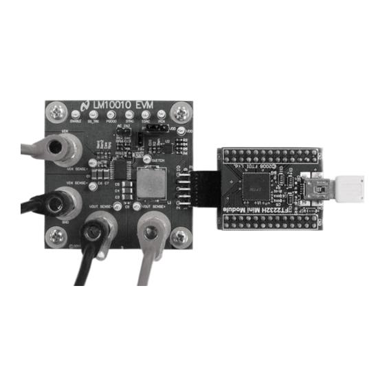
This evaluation module provides a VID interface to test the LM10010 and its control of an LM21215A-1
buck regulator. The LM21215A-1 is capable of driving up to 15A of continuous load current with excellent
output voltage accuracy due to its ±1% internal reference and high gain error amplifier. This device also
features a clock synchronization input that allows the switching frequency to be synchronized to an
external clock source. In this evaluation board, the LM10010 is used to control and adjust the output
voltage through its 4-pin VID interface. The input voltage can be operated from 2.97V to 5.5V. On power-
up, the output voltage defaults to 1.0V. The evaluation board allows for control of the LM21215A-1 output
voltage from 0.7V to 1.1V in 6.4mV steps. The evaluation board also includes a 10-pin header used for
communication with the LM10010. A communications dongle is provided along with software to control the
output voltage through a graphical user interface (GUI) and an USB port. This application note describes
the various functions of the board, how to test and evaluate it, and how to use the GUI design tool to
change the components for a specific application. Please check LM10010 VID Voltage Programmer for
Point of Load Regulator(SNVS717) data sheet for the latest software and data sheet information. For
more information on the LM21215A-1 and its operation, please consult the LM21215A-1 15A High
Efficiency Synchronous Buck Regulator with Frequency Synchronization (SNOSB87) data sheet and the
AN-2131 LM21215A-1 Evaluation Board (SNVA477) evaluation board application note.
3
PCB Features
•
Input voltage range: 3.0V to 5.5V
•
Programmable output voltage: 0.7V to 1.1V
•
Over current protection: 17A
•
PCB Size: 2.1" x 2.1"
•
Solution Size: 1.0" x 1.0"
•
USB connection through communications dongle
•
Software control with graphical user interface
All trademarks are the property of their respective owners.
SNVA498B – July 2011 – Revised May 2013
Submit Documentation Feedback
AN-2176 LM10010 Evaluation Board
Copyright © 2011–2013, Texas Instruments Incorporated
User's Guide
SNVA498B – July 2011 – Revised May 2013
AN-2176 LM10010 Evaluation Board
1
Advertisement
Table of Contents

Related Manuals for Texas Instruments LM10010


Summary of Contents for Texas Instruments LM10010
- Page 1 AN-2176 LM10010 Evaluation Board LM10010 Overview The LM10010 is a precision, digitally programmable device used to control the output voltage of a DC/DC converter. The LM10010 outputs a DC current inversely proportional to a 6-bit input word. This current DAC output connects to the feedback pin of a buck converter in order to adjust its output voltage to a desired range and resolution set by the user.
-
Page 2: Evaluation Board Schematic
USB port on the computer for software control. To start using the LM10010 evaluation module, the first step is to connect the LM10010 board to its power supply while limiting the supply current to ensure that everything is connected correctly. Separately, the dongle is connected to the computer with the USB cable and the software is installed onto the computer. -
Page 3: Over Current Protection
Some voltage supplies can exhibit severe voltage overshoot during high current transients. If a supply overshoots above 6.0V, damage to the LM21215A-1 or the LM10010 can occur. For these supplies, a large capacitor across the terminals of the supply (1000µF) can alleviate this problem. -
Page 4: Connection Descriptions
This terminal block controls the source of power for the LM10010. If a jumper is connected between pins 1 and 2, then the LM10010 supply comes from PVIN. If the jumper is connected from pins 2 and 3, then the LM10010 derives power from an external connection to VDD. -
Page 5: Theory Of Operation
This allows for the V voltage to increment up with the VID code. For a more in-depth analysis of the circuit, see the LM10010 data sheet. Table 1 shows the codes and some of the resultant values of IDAC current and corresponding regulator output voltage for the default resistor values on the evaluation board. -
Page 6: Evaluation Board
First, the user can set a constant output voltage for the point of load with either a voltage or a code. Second, the output can be changed dynamically, ramping through different voltages as the LM10010 counts through a preset sequence. The LM10010 software panel is shown in Figure 3 below. - Page 7 This calculates the theoretical maximum output voltage, minimum output voltage and the resolution of the LM10010 steps. If the values are changed to test the program but not changed on the board, a button is provided to re- enter the default values provided for the original board.
-
Page 8: Select Operation
Control Software www.ti.com Figure 5. LM10010 Board Values Tab 10.3 Select Operation Once the board values are set (or the defaults are chosen), the user can choose the mode of operation of the evaluation module. In the Select Operation Panel, shown in... - Page 9 The Update Graph button is used to show a sample of the expected the output waveform in the Plotter panel of the software. Please note that the LM10010 can be run faster than with the 25 ms minimum delay time set in the software. This limitation is set by the timing of the USB communications of the dongle.
- Page 10 Plotter Panel of the LM10010 software. Vout Plot box shows the expected output voltage, the Code Plot box shows the current code, and the Count Delay box shows the delay between updates in the count used in the Set Dynamic Voltage panel.
- Page 11 NY PMS 440 0025 PH Nylon, Philips panhead H5, H6, H7, H8 Standoff, Hex, 0.5"L #4-40 Nylon Keystone Electronics 1902C SNVA498B – July 2011 – Revised May 2013 AN-2176 LM10010 Evaluation Board Submit Documentation Feedback Copyright © 2011–2013, Texas Instruments Incorporated...
-
Page 12: Pcb Layout
Figure 11. Top Layer (Copper planes outlined in grey) Figure 12. Mid Layer1 Figure 13. Mid Layer2 Figure 14. Bottom Layer AN-2176 LM10010 Evaluation Board SNVA498B – July 2011 – Revised May 2013 Submit Documentation Feedback Copyright © 2011–2013, Texas Instruments Incorporated... -
Page 13: Regulatory Compliance Information
Any exceptions to this are strictly prohibited and unauthorized by Texas Instruments unless user has obtained appropriate experimental/development licenses from local regulatory authorities, which is responsibility of user including its acceptable authorization. - Page 14 FCC Interference Statement for Class B EVM devices This equipment has been tested and found to comply with the limits for a Class B digital device, pursuant to part 15 of the FCC Rules. These limits are designed to provide reasonable protection against harmful interference in a residential installation. This equipment generates, uses and can radiate radio frequency energy and, if not installed and used in accordance with the instructions, may cause harmful interference to radio communications.
- Page 15 Also, please do not transfer this product, unless you give the same notice above to the transferee. Please note that if you could not follow the instructions above, you will be subject to penalties of Radio Law of Japan. Texas Instruments Japan Limited (address) 24-1, Nishi-Shinjuku 6 chome, Shinjuku-ku, Tokyo, Japan http://www.tij.co.jp...
- Page 16 FDA Class III or similar classification, then you must specifically notify TI of such intent and enter into a separate Assurance and Indemnity Agreement. Mailing Address: Texas Instruments, Post Office Box 655303, Dallas, Texas 75265 Copyright © 2013, Texas Instruments Incorporated...
-
Page 17: Important Notice
IMPORTANT NOTICE Texas Instruments Incorporated and its subsidiaries (TI) reserve the right to make corrections, enhancements, improvements and other changes to its semiconductor products and services per JESD46, latest issue, and to discontinue any product or service per JESD48, latest issue.
Need help?
Do you have a question about the LM10010 and is the answer not in the manual?
Questions and answers