
Related Manuals for Texas Instruments LM5175EVM-HP


Summary of Contents for Texas Instruments LM5175EVM-HP
- Page 1 LM5175 Wide VIN 4-Switch Buck-Boost Converter High Power Evaluation Module User's Guide Literature Number: SNVU465 February 2015...
-
Page 2: Table Of Contents
Test Data and Performance Curve ........................Efficiency ..................Typical Operation Waveforms ........................Soft Start ....................LM5175EVM-HP Schematic ................... Assembly Drawings and Layout ................... LM5175EVM-HP Bill of Materials Table of Contents SNVU465 – February 2015 Submit Documentation Feedback Copyright © 2015, Texas Instruments Incorporated... - Page 3 Mid-Layer 2 ......................... Mid-Layer 3 ......................... Mid-Layer 4 ........................ Bottom Layer List of Tables ....................Connectors and Test Points ..................LM5175EVM-HP Bill of Materials SNVU465 – February 2015 List of Figures Submit Documentation Feedback Copyright © 2015, Texas Instruments Incorporated...
-
Page 4: Introduction
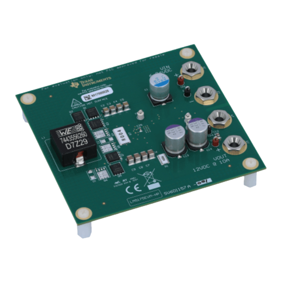
The output voltage is adjustable from 0.8 V to 55 V. The LM5175EVM-HP high power EVM is fully assembled and tested platform for evaluating the operation and performance of the LM5175 buck-boost controller. The LM5175EVM-HP has an input voltage range from 6 V to 36 V, the output voltage is set as 12 V using an external feedback resistor divider. -
Page 5: Connector, Test Point And Selection Switch Descriptions
TP3 (VOUT) Output voltage positive test point TP4 (GND) Output voltage return test point TP5 (PGOOD) Power Good output TP6 (BIAS) BIAS voltage test point TP7(SYNC) SYNC input SNVU465 – February 2015 Submit Documentation Feedback Copyright © 2015, Texas Instruments Incorporated... -
Page 6: Selection Switch Descriptions
No connection in position 3, do not apply switch to this position. Test Setup and Procedure Test Setup Figure 1 shows a typical test setup to evaluate the LM5175EVM-HP Figure 1. Typical EVM Connection Diagram SNVU465 – February 2015 Submit Documentation Feedback... -
Page 7: Test Procedure
Test Data and Performance Curve Efficiency Figure 2. Efficiency vs. Output Current Figure 3. Efficiency and Power Loss vs. Input Voltage SNVU465 – February 2015 Submit Documentation Feedback Copyright © 2015, Texas Instruments Incorporated... -
Page 8: Typical Operation Waveforms
Typical Operation Waveforms Figure 5. Typical Operation Waveforms (VIN=12 V, IOUT=2 Figure 4. Typical Operation Waveforms (VIN=9 V, IOUT=2 Figure 6. Typical Operation Waveforms (VIN=15 V, IOUT=2 A) SNVU465 – February 2015 Submit Documentation Feedback Copyright © 2015, Texas Instruments Incorporated... -
Page 9: Soft Start
Test Data and Performance Curve www.ti.com Soft Start Figure 7. Turn-on Waveforms (VIN=24 V, IOUT=0 A) Figure 8. Turn-on Waveforms (VIN=24 V, IOUT=10 A) SNVU465 – February 2015 Submit Documentation Feedback Copyright © 2015, Texas Instruments Incorporated... -
Page 10: Lm5175Evm-Hp Schematic
LM5175EVM-HP Schematic www.ti.com LM5175EVM-HP Schematic Figure 9. 4-Switch Buck-Boost Converter Schematic SNVU465 – February 2015 Submit Documentation Feedback Copyright © 2015, Texas Instruments Incorporated... -
Page 11: Assembly Drawings And Layout
Assembly Drawings and Layout www.ti.com Assembly Drawings and Layout Figure 12 through Figure 17 show the design of the LM5175EVM-HP PCB. Figure 10. Top Assembly Figure 11. Assembly Bottom SNVU465 – February 2015 Submit Documentation Feedback Copyright © 2015, Texas Instruments Incorporated... -
Page 12: Top Layer
Assembly Drawings and Layout www.ti.com Figure 12. Top Layer Figure 13. Mid-Layer 1 SNVU465 – February 2015 Submit Documentation Feedback Copyright © 2015, Texas Instruments Incorporated... -
Page 13: Mid-Layer
Assembly Drawings and Layout www.ti.com Figure 14. Mid-Layer 2 Figure 15. Mid-Layer 3 SNVU465 – February 2015 Submit Documentation Feedback Copyright © 2015, Texas Instruments Incorporated... -
Page 14: Mid-Layer
Assembly Drawings and Layout www.ti.com Figure 16. Mid-Layer 4 Figure 17. Bottom Layer SNVU465 – February 2015 Submit Documentation Feedback Copyright © 2015, Texas Instruments Incorporated... -
Page 15: Lm5175Evm-Hp Bill Of Materials
LM5175EVM-HP Bill of Materials www.ti.com LM5175EVM-HP Bill of Materials Table 2. LM5175EVM-HP Bill of Materials Ref Des Quantity Description Part Number Manufacturer Printed Circuit Board SV601157 CAP, AL, 180 µF, 50 V, +/- 20%, 0.019 PCR1H181MCL1GS Nichicon ohm, SMD C2, C3, C4, C5 CAP, CERM, 10 µF, 50 V, +/- 10%, X7R,... - Page 16 LM5175EVM-HP Bill of Materials www.ti.com Table 2. LM5175EVM-HP Bill of Materials (continued) Ref Des Quantity Description Part Number Manufacturer RES, 93.1 k, 1%, 0.1 W, 0603 RES, 100 k, 1%, 0.1 W, 0603 RES, 20.0k ohm, 1%, 0.1W, 0603 S1, S2, S3 Slide SW, SPDT 0.1A 50VDC...
- Page 17 STANDARD TERMS AND CONDITIONS FOR EVALUATION MODULES Delivery: TI delivers TI evaluation boards, kits, or modules, including any accompanying demonstration software, components, or documentation (collectively, an “EVM” or “EVMs”) to the User (“User”) in accordance with the terms and conditions set forth herein. Acceptance of the EVM is expressly subject to the following terms and conditions.
- Page 18 FCC Interference Statement for Class B EVM devices NOTE: This equipment has been tested and found to comply with the limits for a Class B digital device, pursuant to part 15 of the FCC Rules. These limits are designed to provide reasonable protection against harmful interference in a residential installation.
- Page 19 【無線電波を送信する製品の開発キットをお使いになる際の注意事項】 本開発キットは技術基準適合証明を受けておりません。 本製品のご使用に際しては、電波法遵守のため、以下のいずれかの措置を取っていただく必要がありますのでご注意ください。 1. 電波法施行規則第6条第1項第1号に基づく平成18年3月28日総務省告示第173号で定められた電波暗室等の試験設備でご使用 いただく。 2. 実験局の免許を取得後ご使用いただく。 3. 技術基準適合証明を取得後ご使用いただく。 なお、本製品は、上記の「ご使用にあたっての注意」を譲渡先、移転先に通知しない限り、譲渡、移転できないものとします。 上記を遵守頂けない場合は、電波法の罰則が適用される可能性があることをご留意ください。 日本テキサス・インスツルメンツ株式会社 東京都新宿区西新宿6丁目24番1号 西新宿三井ビル 3.3.3 Notice for EVMs for Power Line Communication: Please see http://www.tij.co.jp/lsds/ti_ja/general/eStore/notice_02.page 電力線搬送波通信についての開発キットをお使いになる際の注意事項については、次のところをご覧くださ い。http://www.tij.co.jp/lsds/ti_ja/general/eStore/notice_02.page SPACER EVM Use Restrictions and Warnings: 4.1 EVMS ARE NOT FOR USE IN FUNCTIONAL SAFETY AND/OR SAFETY CRITICAL EVALUATIONS, INCLUDING BUT NOT LIMITED TO EVALUATIONS OF LIFE SUPPORT APPLICATIONS.
- Page 20 Notwithstanding the foregoing, any judgment may be enforced in any United States or foreign court, and TI may seek injunctive relief in any United States or foreign court. Mailing Address: Texas Instruments, Post Office Box 655303, Dallas, Texas 75265 Copyright © 2015, Texas Instruments Incorporated...
- Page 21 IMPORTANT NOTICE Texas Instruments Incorporated and its subsidiaries (TI) reserve the right to make corrections, enhancements, improvements and other changes to its semiconductor products and services per JESD46, latest issue, and to discontinue any product or service per JESD48, latest issue.
Need help?
Do you have a question about the LM5175EVM-HP and is the answer not in the manual?
Questions and answers