Table of Contents
Advertisement
Quick Links
Advertisement
Table of Contents

Subscribe to Our Youtube Channel
Related Manuals for Ametek Magnetrol SOLITEL


Summary of Contents for Ametek Magnetrol SOLITEL
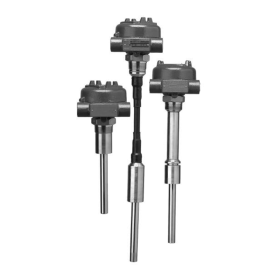
- Page 1 Installation and Operating Manual Solitel Vibrating Rod evel Switch...
- Page 2 Always shut off the power supply before touching any components. Although high voltage is not present in this Copyright © 2022 AMETEK Magnetrol USA, LLC. system, it may be present in other systems. All rights reserved.
-
Page 3: Principle Of Operation
Introduction The Solitel Vibrating Rod Level Switch provides reliable ® level detection of bulk solids and powders. This compact, integral switch is suitable for high or low level detection in hoppers and silos. It may also be used for plugged chute detection. -
Page 4: Electrostatic Discharge (Esd) Handling Procedure
The SOLITEL switch is mounted to the vessel using a ⁄ " NPT threaded connection. • Ensure that the tip of the probe is located at the desired switching point giving consideration to the slope angle of the material. • The switch may be installed vertically or horizontally (at a downward angle) as shown in Figure 1 on page 3. - Page 5 2. Use a grounding wrist strap when installing and removing circuit boards. A grounded workstation is also recommended. 3. Handle printed circuit boards only by the edges. Do not touch components or connector pins. 4. Ensure that all electrical connections are completely made and none are partial or floating.
- Page 6 Power Material Level Fail-Safe Jumper LED Color Relay Coil Relay Terminal NO to CO NC to CO 6–7 7–8 High position Green De-energized Open Closed B position Energized Closed Open position Energized Closed Open B position Green De-energized Open Closed Fail High/Low De-energized...
-
Page 7: Reference Information
Reference Information Troubleshooting SOLITEL is a simple and reliable device. However, care must be taken to avoid impacting or damaging the vibrat- ing probe. In the event the SOLITEL stops vibrating, the following procedure will identify if the problem is with the electron- ic module or with the sensor: Disconnect the wires going to the sensor. -
Page 8: Agency Approvals
5. Connect a digital multimeter between points MP5 on the back of the module and ground connection (terminal 3 on the electronic module) or the body of the vibrating probe. See Figure 7 on page 7. 6. Adjust potentiometer P2 on the rear of the electronic mod- ule to obtain a voltage between 0.4 volts and 1.0 volts. -
Page 9: Specification
Specifications 3.4.1 Performance Description Specification Input voltage 110 VAC +10/-15% 140 F (60 C) 24 VDC (±10%) Power consumption Less than or equal to 3 VA 95 F (35 C) Operation frequency 350 Hz Output relay SPDT 8 amp @ 250 VAC -40 F 320 F 167 F... -
Page 10: Dimensional Specifications
3.4.2 Physical DIMENSIONAL SPECIFICATIONS inches (mm) 4.63 (117) Dia. 3.44 (87) 4.63 3.44 (87) Rotation clearance (117) Dia. Rotation clearance 2.75 " NPT 3.63 (69) 2.75 (69) plugged 3.63 (92) (92) " " NPT Conduit " connection Conduit connection plugged (38) (38) "... -
Page 11: Probe Type
Model Numbers 3.5.1 Solitel Level Switch Standard and Extended Rigid Probe ® DESIGN TYPE Standard, length in inches Enhanced performance*, length in inches *Recommended for temperatures up to +320° F (+160° C) or for sticky materials. PROBE TYPE Standard rigid, 8.25" (21 cm) length Extended rigid INPUT VOLTAGE 110 V C... - Page 12 No claims for misapplication, labor, direct or consequen- tial damage will be allowed. 705 Enterprise Street • Aurora, Illinois 60504-8149 USA 630.969.4000 • info.magnetrol@ametek.com • magnetrol.com BULLETIN: 56-601.8 EFFECTIVE: July 2019 Copyright © 2022 AMETEK Magnetrol USA, LLC SUPERSEDES: October 2016...
Need help?
Do you have a question about the Magnetrol SOLITEL and is the answer not in the manual?
Questions and answers