Table of Contents
Advertisement
Quick Links
Advertisement
Table of Contents

Related Manuals for Ametek MAGNETROL T20


Summary of Contents for Ametek MAGNETROL T20
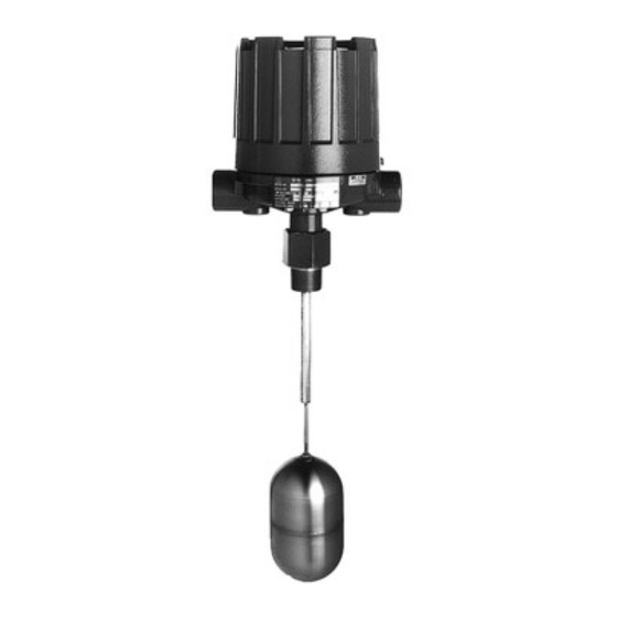
- Page 1 Top Mounting T20 and T21 Installation and Operating Manual Liquid Level Switches...
- Page 2 AMETEK LMS will repair or replace the NOTES control at no cost to the purchaser (or owner) Notes contain information that augments or other than transportation.
-
Page 3: Table Of Contents
Top Mounting Liquid Level Switches Table of Contents 1.0 Introduction 5.0 Reference Information 1.1 Principle of Operation........4 5.1 Troubleshooting..........12 5.1.1 Check switch mechanism....12 2.0 Installation 5.1.2 Check complete unit......12 2.1 Unpacking ............4 5.2 Agency Approvals ........14 2.2 Critical alarm function ........5 5.2.1 Specific Conditions of Use ....18 2.3 Mounting............5 5.3 Specifications ..........19... -
Page 4: Introduction
Introduction T20 and T21 level switches are float operated units designed for top mounting to a tank or vessel by means of threaded or flanged pipe connections. T20 standard units are equipped with a single switch mech- anism for high or low level alarm or control applica- tions. -
Page 5: Critical Alarm Function
Critical alarm function It is recommended that for critical alarm functions, an additional level switch be installed as a high–high or low–low level alarm for maximum protection. Mounting Caution: Operation of all buoyancy type level devices should be done in such a way as to minimize the action of dynamic forces on the float or displacer sensing element. -
Page 6: Wiring
Wiring Caution: All Top Mounting units are shipped from the factory with the enclosing tube tightened and the switch housing set screw locked to the enclosing tube. Failure to loosen the set screw prior to repositioning the supply and output connections may cause the enclosing tube to loosen, resulting in possible leakage of the process liquid or vapor. -
Page 7: Switch Differential Adjustment
Caution: In hazardous areas, do not power the unit until the conduit is sealed and the enclosure cover is screwed down securely. 7. Replace housing cover. 8. If control has been furnished with an explosion proof or moisture proof switch housing, it must be sealed at the conduit outlet with a suitable compound or non-hard- ening sealant to prevent entrance of air. - Page 8 1. Determine what change in differential is necessary. 2. Make sure power source is turned off. 3. Unscrew and remove switch housing cover. Switch housing Enclosing tube cover 4. Disconnect power supply wires from switch mecha- Refer to Figures 6 and 7 nism.
- Page 9 For access to bottom Maximum gap setting Slight play (gap) jam nuts, mark position, (Applies to models having must be allowed 0.50" remove top jam nuts, a single switch mechanism Replace in (.03" [.8 mm] typical) (13 mm) washer, and attracting with a single magnet same position sleeve.
-
Page 10: Preventive Maintenance
Preventive Maintenance Periodic inspections are a necessary means to keep your level control in good working order. This control is a safety device to protect the valuable equipment it serves. Therefore, a systematic program of “preventive maintenance” must be implemented when the control is placed into service. -
Page 11: Inspect Entire Unit Periodically
5. On units with pneumatic switches, air (or gas) lines subjected to vibration, may eventually crack or become loose at connections causing leakage. Check lines and connections carefully and repair or replace, if necessary. NOTE: As a matter of good practice, spare switches should be kept on hand at all times. -
Page 12: Reference Information
Reference Information Troubleshooting Usually the first indication of improper operation is fail- ure of the controlled equipment to function, (i.e.: pump will not start (or stop), signal lamps fail to light, etc.) When these symptoms occur, whether at time of installation or during routine service thereafter, check the following potential external causes first. - Page 13 Caution: With electrical power on, care should be taken to avoid contact with switch leads and connections at terminal block. 2. If controlled equipment responds to manual actuation test, trouble may be located in the level sensing portion of the control–float(s), stem(s), and magnetic attraction sleeve(s).
-
Page 14: Agency Approvals
Agency Approvals EMC directive 2014/30/EU (electromagnetic compatibility) The following standard has been applied: EN 61326-1:2013-(Low Voltage Directive-CE) Y 4X APPROVED 705 ENTERPRISE ST AURORA, IL 60504 USA MODEL NO SERIAL NO AMB TEMP: -40°C TO +70°C INPUT: MAX.PRESS: OUTPUT: 005-8047-003 Approval: FM Type 4X Housing Material: Carbon Steel/Aluminum Y 4X... - Page 15 705 ENTERPRISE ST AURORA, IL 60504 USA MADE BY: 9240 ZELE BELGIUM MODEL NO SERIAL NO FM21ATEX0060X\FM21UKEX0206X II 2 G Ex db IIC T6...T1 Gb TAG NO IECEx FMG 21.0032X MAX PRESS MIN SG Ex db IIC T6...T1 Gb VAC/A VDC/A CABLE ENTRY AMB TEMP: -40 C TO 70 C...
- Page 16 Maximum Pressure Ratings: These are the ranges of process pressure ranges based on each individual model as mention in each individual manual. Nominal Thickness Minimum Thickness Pressure Rating for (in) (in) 316 SST Version (psig) 0.035 0.0295 1300 0.065 0.0595 2710 0.093 0.087...
- Page 17 Switch Ratings RATING SWITCH SWITCH PROCESS LOAD VOLTS AC VOLTS DC SERIES TYPE TEMP RANGE Non-Inductive Amp 15.00 15.00 15.00 6.00 0.50 0.25 -40 to +250 °F Snap Inductive Amp 15.00 15.00 15.00 5.00 0.05 0.03 (-40 to +121 °C) Horseower —...
-
Page 18: Specific Conditions Of Use
Item Description/Ratings Installation and Erection TO PREVENT IGNITION OF HAZARDOUS ATMOSPHERES. DISCONNECT DEVICE FROM SUPPLY CIRCUIT BEFORE OPENING. KEEP ASSEMBLY TIGHTLY CLOSED WHEN IN OPERATION. Before attempting to remove a switch mechanism, be certain to pull disconnect switch or otherwise assure that electrical circuit through control is de-energized. -
Page 19: Specifications
Specifications 5.3.1 Physical inches (mm) * These dimensions increase by 2.19 (55) 6.25* 6.25* when unit is supplied 7.94* (158) (158) 7.94* with an HS switch with (201) (201) terminal block. 2.44 1.81 (45) Ref. (61) 1" NPT Distance to Distance to actuating level actuating level... -
Page 20: Replacement Parts
Replacement Parts 5.4.1 Model T20 Parts Identification Item Description Housing cover Housing base Switch mechanism Attraction sleeve Jam nuts Guide washer(s) Float stem Float Adaptor bushing/guide tube assembly Enclosing tube gasket Enclosing tube Mounting flange 44-604 Top Mounting Liquid Level Switches... -
Page 21: Model T20
5.4.1.1 Model T20 T20-1 T20-4 Housing cover See below Housing base See below Switch mechanism See below Stem kit: includes items 4, 5, 6, & 7 Consult factory Float: 3.00" ¥ 5.00" Z07-1202-003 3.50" ¥ 6.00" Z07-1202-009 4.00" Z07-1102-008 4.50" Z07-1102-009 Adaptor bushing/guide tube assembly Consult factory... -
Page 22: Model T21 Parts Identification
Replacement Parts 5.4.2 Model T21 Parts Identification Item Description Housing cover Housing base Switch mechanism Upper attraction sleeve Jam nuts Guide washer(s) Upper stem assembly Lower float Lower attraction sleeve, stop tube, and washers Retaining rings Upper float and tube assembly Adaptor bushing Enclosing tube gasket Enclosing tube... -
Page 23: Model T21
5.4.2.1 Model T21 T21-1 T21-4 Housing cover See below Housing base See below Switch mechanism See below Float stem kit: includes items 4, 5, 6, & 7 Consult factory Lower float: 3" ¥ 5" Z07-1201-003 Z07-1202-003 4.00" Z07-1101-015 Z07-1102-008 4.50" Z07-1102-009 Upper float and tube assembly kit: includes items 9, 10, &... -
Page 24: Model Numbers
Model Numbers 5.5.1 Model T20 IMPORTANT: Actuating level(s), in either the rising or falling state, and specific gravity must be provided upon placement of order. MODEL NUMBER CODE AND MATERIALS OF CONSTRUCTION Model No. Set Points Tank Connection Float and Trim Sleeve T20-1 Carbon steel... - Page 25 ELECTRIC SWITCH MECHANISM AND ENCLOSURE T20-1 Models T20-4 Models Process ➃ Aluminum Enclosure ➄≈ Temperature Switch Contacts Range FM (US/CA) FM (US/CA) FM (US/CA) FM (US/CA) Description Points ATEX/ IECEx ATEX/ IECEx Groups C&D Group B Groups C&D Group B °F (°C) 1"...
-
Page 26: Model T21
Model Numbers 5.5.2 Model T21 IMPORTANT: Actuating level(s), in either the rising or falling state, and specific gravity must be provided upon placement of order. MODEL NUMBER CODE AND MATERIALS OF CONSTRUCTION Model No. Set Points Tank Connection Float and Trim Sleeve T21-1 Carbon steel... - Page 27 ELECTRIC SWITCH MECHANISM AND ENCLOSURE T21-1 Models T21-4 Models Process ➃ Aluminum Enclosure ➄≈ Temperature Switch Contacts FM (US/CA) FM (US/CA) FM (US/CA) FM (US/CA) Range Description Points ATEX / IECEx ATEX / IECEx Groups C&D Group B Groups C&D Group B °F (°C) 1"...
- Page 28 Prepaid transporta- is available through Magnetrol’s local representa- tion. AMETEK LMS will repair or replace the control tive or by contacting the factory. Please supply the at no cost to the purchaser (or owner) other than...
Need help?
Do you have a question about the MAGNETROL T20 and is the answer not in the manual?
Questions and answers