Table of Contents
Advertisement
Quick Links
Advertisement
Table of Contents

Related Manuals for Ametek MAGNETROL SOLITEL Series


Summary of Contents for Ametek MAGNETROL SOLITEL Series
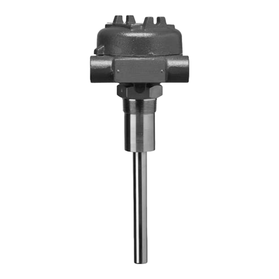
- Page 1 Installation and Operating Manual for Solitel ® Vibrating Rod Level Switch...
- Page 2 NOTES Warranty Notes contain information that augments or All AMETEK LMS electronic level and flow controls clarifies an operating step. Notes do not normally are warranted free of defects in materials or contain actions. They follow the procedural steps workmanship for eighteen months from the date of to which they refer.
-
Page 3: Principle Of Operation
Introduction The Solitel Vibrating Rod Level Switch provides reli- ® able level detection of bulk solids and powders. This compact, integral switch is suitable for high or low level detection in hoppers and silos. It may also be used for plugged chute detection. -
Page 4: Electrostatic Discharge (Esd) Handling Procedure
Figure 4 Electrostatic Discharge (ESD) Handling Procedure AMETEK LMS electronic instruments are manufactured to the highest quality standards. These instruments utilize electronic components which may be damaged by static electricity present in most work environments. The following steps are recommended to reduce the risk of component failure due to electrostatic discharge: 1. - Page 5 3. Handle printed circuit boards only by the edges. Do not touch components or connector pins. 4. Ensure that all electrical connections are completely made and none are partial or floating. Ground all equip- ment to a good earth ground wiring. Wiring Manually position the housing in the correct direction to allow for easy wiring.
- Page 6 Relay Terminal Fail-Safe Power Material Level LED Color Relay Coil NO to CO NC to CO Jumper 6–7 7–8 High A position Green De-energized Open Closed B position Energized Closed Open High A position Energized Closed Open B position Green De-energized Open Closed...
-
Page 7: Reference Information
Reference Information Troubleshooting Solitel is a simple and reliable device. However, care must be taken to avoid impacting or damaging the vibrating probe. In the event the Solitel stops vibrating, the following procedure will identify if the problem is with the elec- tronic module or with the sensor: Disconnect the wires going to the sensor. -
Page 8: Agency Approvals
5. Connect a digital multimeter between points MP5 on the back of the module and ground connection (terminal 3 on the electronic module) or the body of the vibrating probe. See Figure 7 on page 7. 6. Adjust potentiometer P2 on the rear of the electronic module to obtain a voltage between 0.4 volts and 1.0 volts. -
Page 9: Specifications
Specifications 110 VAC +10/-15% Input voltage 220 VAC +10/-15% 24 VDC (±10%) Power consumption Less than or equal to 3 VA Operation frequency 350 Hz SPDT 8 amp @ 250 VAC Output relay SPDT 1 amp @ 24 VDC Time delay 4 to 10 seconds (depending on sensitivity adjustment) Process connection ⁄... - Page 10 3.4.2 Physical DIMENSIONAL SPECIFICATIONS — inches (mm) 4.63 3.44 (87) (117) Dia. Rotation clearance 4.63 (117) Dia. 3.44 (87) 2.75 (69) 3.63 Rotation clearance (92) " 2.75 " NPT 3.63 (69) Conduit plugged " (92) connection plugged (38) " process connection "...
-
Page 11: Model Numbers
Model Numbers 3.5.1 Standard and Extended Rigid Probe 2 | DESIGN TYPE Standard, -4 to +230 °F (-20 to +110 °C), insertion length in inches Enhanced performance, -40 to +320 °F (-40 to +160 °C), insertion length in inches 3 | PROBE TYPE Standard rigid probe, 8.25"... -
Page 12: Service Policy
Controls returned under factory, prior to the material’s return. This is available our service policy must be returned by Prepaid through a AMETEK LMS local representative or by transportation. AMETEK LMS will repair or replace contacting the factory. Please provide the following...
Need help?
Do you have a question about the MAGNETROL SOLITEL Series and is the answer not in the manual?
Questions and answers