
Subscribe to Our Youtube Channel
Related Manuals for Ametek Magnetrol Thermatel TD1


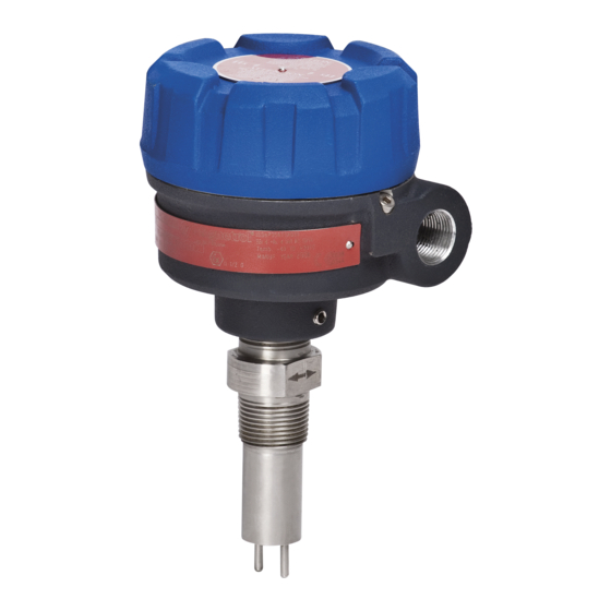
Summary of Contents for Ametek Magnetrol Thermatel TD1
- Page 1 THERMATEL ® TD1/TD2 ODEL Installation and Operating Manual Thermal Dispersion Flow/Level/Interface Switch Model TD1 Model TD2 with twin tip sensor with spherical tip sensor Model TD2 with low flow body sensor...
- Page 2 UNPACKING Unpack the instrument carefully. Make sure all components Nameplate: have been removed from the foam protection. Inspect all - partnumber amplifier - sensor components for damage. Report any concealed damage to - serial n° the carrier within 24 hours. Check the contents of the car- - tag n°...
-
Page 3: Relay Connections
WIRING 8A DPDT Relay 24 V DC (± 20 %) Power POWER HEATER TEMP COMP MEDIA RANGE FAILSAFE FAULT ALARM MODEL TD1 1 - white 2 - black TD1 Wiring 3 - red 4 - green 5 - orange 8A DPDT Relay 6 - blue or 1A H.S. - Page 4 SETUP AND FUNCTIONS Indication and functions MODEL TD1 FAIL-SAFE (TD1/TD2): HLFS (High Level Fail-safe): ALARM LED Relay is energized when flow < setpoint or sensor dry (or Red LED on = alarm POWER LED in the low conductive liquid). Red LED blinks = error Unit powered = green LED on Relay is de-energized when flow ≥...
- Page 5 SETUP AND FUNCTIONS Switch setup For factory calibrated devices, the switch setup and calibration is completed by MAGNETROL for optimal performance in your application. The dip-switch settings and/or potentiometers should only be adjusted for troubleshooting pur- poses if the factory calibration was not sufficient. The switch settings are set at MAGNETROL during setup.
- Page 6 CALIBRATION For factory calibrated devices, the switch setup and calibration is completed by MAGNETROL for optimal performance in your application. The dip-switch settings and/or potentiometers should only be adjusted for troubleshooting pur- poses if the factory calibration was not sufficient. NOTE: Ensure that settings on page 3 have been verified before calibrating this unit.
-
Page 7: Fault Indication
FAULT INDICATION TD1/TD2 have continuous diagnostics to ensure that the signal from the sensor is within a select range. If the electronics detect an “out of range” signal, the switch has registered an instrument error. TD1: Alarm LED blinks and the relay de-energizes. TD2: 3,6 mA signal when unit is set for low level fail-safe. -
Page 8: Resistance Values
TROUBLESHOOTING Symptom Application Action* Switch indicates a fault Liquid Flow – Flow Turn off TEMP COMP (TD1) / TC (TD2) (red LED will blink) Present Light goes off—operate in this mode Light stays on—check resistance to determine if a problem exists with the probe or electronics. -
Page 9: Replacement Parts
REPLACEMENT PARTS Note: The switch will require recalibration (see page 6) following probe or electronics replacement. Probe replacement INTEGRAL ELECTRONICS Removal of probe 1. Make sure the power source is turned off. 2. Unscrew and remove housing cover. 3. Remove the bezel by: a. - Page 10 REPLACEMENT PARTS E X P E D I T E S H I P P L A N ( E S P ) Several parts are available for quick shipment, within max. 1 week after factory receipt of purchase order, through the Expedite Ship Plan (ESP).
- Page 11 REPLACEMENT PARTS Replacement parts – Model TD2 Partn°: Serial n°: T D 2 See nameplate, always provide complete partn° and Digit in partn°: 8 9 10 serial n° when ordering spares. X = product with a specific customer requirement INTEGRAL ELECTRONICS REMOTE ELECTRONICS (1) Housing cover (2) Electronic module...
-
Page 12: Model Identification
MODEL IDENTIFICATION A complete measuring system consists of: 1. THERMATEL electronics ® 2. Connecting cable (only applicable for remote mount TD2 units) 3. THERMATEL sensor ® 4. Optional: Order code for thread-on mounting flanges 5. Optional: Retractable probe assembly, consult factory for details 6. - Page 13 MODEL IDENTIFICATION 1. Code for Thermatel TD2 electronics with housing for industrial use ® 1 2 3 | BASIC MODEL NUMBER T D 2 Electronics with continuous LED indication and mA output POWER SUPPLY 240 V AC (100-264 V AC) 24 V DC (±...
- Page 14 CONNECTIONS Insertion length Insertion BSP connection length Insertion length NPT connection Threaded Welded flange ASME - EN DIMENSIONS IN mm (inches) – TMA/TMB/TMC/TMD Standard: 46 (1.81) Standard: 60 (2.36) With heat extension: 223 (8.78) With heat extension: 223 (8.78) Insertion length BSP connection Insertion length Insertion...
- Page 15 MODEL IDENTIFICATION 3. Order code for Thermatel TD1/TD2 – STANDARD SENSOR ® 1 2 3 | BASIC MODEL NUMBER T M A Spherical tip - standard max +120 °C (+250 °F) ¿ T M B Spherical tip - with heat extension max +200 °C (+400 °F) T M C Twin tip...
- Page 16 DIMENSIONS IN mm (inches) – TMH (9.88) (10.00) (10.75) Insertion length Insertion Insertion length length Flanged connection connection connection Ø 21,9 Ø 21,9 (0.86) (0.86) PRESSURE/TEMPERATURE RATING – TMH Maximum process pressure @ +40 °C (+100 °F) @ +120 °C (+250 °F) @ +200 °C (+400 °F) @ +450 °C (+850 °F) 414 bar (6000 psi)
- Page 17 MODEL IDENTIFICATION 3. Order code for Thermatel TD1/TD2 – HIGH TEMPERATURE / HIGH PRESSURE SENSOR ® 1 2 3 | BASIC MODEL NUMBER T M H High temperature / high pressure twin tip – max +450 °C (+850 °F) / max 414 bar (6000 psi) ¿...
- Page 18 MODEL IDENTIFICATION 3. Order code for Thermatel TD1/TD2 – MINI SENSOR ® 1 2 3 | BASIC MODEL NUMBER T M M Mini twin tip – max +120 °C (+250 °F) ¿ TMM sensors can handle process temperatures up to +200 °C (+400 °F) with remote electronics. ¿...
- Page 19 MODEL IDENTIFICATION 3. Order code for Thermatel TD1/TD2 – LOW FLOW BODY SENSOR ® 1 2 3 | BASIC MODEL NUMBER T M L Low flow body – max +120 °C (+250 °F) / max 400 bar (5800 psi) ¿ TML sensors can handle process temperatures up to +200 °C (+400 °F) with remote electronics.
- Page 20 MODEL IDENTIFICATION 4. Optional sensor mounting flanges Thread-on mounting flanges can only be used in combination with 3/4" NPT process connection sensor. Consult factory for other sizes or materials. Thread-on flanges for use with 3/4" NPT-M connections Part No. ASME B16.5 flanges Carbon steel 316/316L SST Hastelloy C...
-
Page 21: Specifications
DIMENSIONS IN mm (inches) – WITH HOUSING FOR INDUSTRIAL USE (4.00) (4.00) without window 113 (4.43) (3.95) with window 123 (4.85) 60 (2.36) (2.75) (0.37) Insertion length (3.75) (4.00) 2 holes max 150 m (500 ft) Ø 9,5 (3.50) cable is ordered separately (0.37) Ø... - Page 22 SPECIFICATIONS Performance Description Specification Response time 1-10 s typical (dependent on sensor type, application and set point) Repeatability < 1 % @ constant temperature Ambient temperature ATEX/IEC Ex d - T4 & non Ex: -40 °C to +70 °C (-40 °F to +160 °F) ATEX/IEC Ex d - T5: -40 °C to +40 °C (-40 °F to +104 °F) Storage: -50 °C to +75 °C (-58 °F to +170 °F) Humidity...
- Page 23 Notes...
-
Page 24: Service Policy
IMPORTANT SERVICE POLICY Owners of Magnetrol products may request the return of a control; or, any part of a control for complete rebuilding or replacement. They will be rebuilt or replaced promptly. Magnetrol International will repair or replace the control, at no cost to the purchaser, (or owner) other than transportation cost if: a.
Need help?
Do you have a question about the Magnetrol Thermatel TD1 and is the answer not in the manual?
Questions and answers