Table of Contents
Advertisement
Quick Links
Quick Installation Guide
Moxa Industrial Media Converter
Moxa Americas:
Toll-free: 1-888-669-2872
Tel:
1-714-528-6777
Fax:
1-714-528-6778
Moxa Europe:
Tel:
+49-89-3 70 03 99-0
Fax:
+49-89-3 70 03 99-99
Moxa India:
Tel:
+91-80-4172-9088
Fax:
+91-80-4132-1045
IMC-21A
Edition 5.1, July 2018
Technical Support Contact Information
www.moxa.com/support
2018 Moxa Inc. All rights reserved.
Moxa China (Shanghai office):
Toll-free: 800-820-5036
Tel:
+86-21-5258-9955
Fax:
+86-21-5258-5505
Moxa Asia-Pacific:
Tel:
+886-2-8919-1230
Fax:
+886-2-8919-1231
P/N: 1802000210023
*1802000210023*
Advertisement
Table of Contents

Subscribe to Our Youtube Channel
Related Manuals for Moxa Technologies IMC-21A IMC-21A


Summary of Contents for Moxa Technologies IMC-21A IMC-21A
- Page 1 IMC-21A Quick Installation Guide Moxa Industrial Media Converter Edition 5.1, July 2018 Technical Support Contact Information www.moxa.com/support Moxa Americas: Moxa China (Shanghai office): Toll-free: 1-888-669-2872 Toll-free: 800-820-5036 Tel: 1-714-528-6777 Tel: +86-21-5258-9955 Fax: 1-714-528-6778 Fax: +86-21-5258-5505 Moxa Europe: Moxa Asia-Pacific: Tel: +49-89-3 70 03 99-0 Tel: +886-2-8919-1230...
-
Page 2: Package Checklist
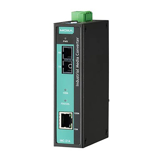
Overview The Moxa Industrial Media Converter IMC-21A series consists of entry- level 10/100BaseT(X) to 100BaseFX media converters that provide a cost-effective solution, and are specially designed for reliable and stable operations in harsh industrial environments. NOTE Throughout this Hardware Installation Guide, we use IMC as an abbreviation for Industrial Media Converter: IMC = Industrial Media Converter Package Checklist... -
Page 3: Panel Layout
Panel Layout 1. DIP switch 2. Reset button 3. Terminal block for power input and grounding 4. Power input LED 5. 100BaseFX (SC/ST connector) port 6. FX port's 100 Mbps LED 7. FX port's FDX/COL LED 8. TP port’s 100 Mbps LED 9. -
Page 4: Mounting Dimensions
Mounting Dimensions DIN-Rail Mounting The aluminum DIN-rail attachment plate should be fixed to the back panel of the IMC-21A when you take it out of the box. If you need to reattach the DIN-rail attachment plate to the IMC-21A, make sure the stiff metal spring is situated towards the top. -
Page 5: Grounding The Moxa Imc
• Use separate paths to route wiring for power and devices. If power wiring and device wiring paths must cross, make sure the wires are perpendicular at the intersection point. • Do not run signal or communications wiring and power wiring in the same wire conduit. -
Page 6: Communication Connections
Communication Connections RJ45 Ethernet Port Connection The IMC-21A has one 10/100BaseT(X) Ethernet port located on the front panel for connecting to Ethernet-enabled devices. Pinouts and cable wiring diagrams for both MDI (NIC-type) and MDI-X (HUB/switch-type) ports for both straight-through and crossover Ethernet cables are shown below: MDI Port Pinouts MDI-X Port Pinouts... - Page 7 Fiber Optic Port Connection The concept behind the SC/ST port and cable is quite straightforward. Suppose you are connecting devices I and II. Contrary to electrical signals, optical signals do not require a circuit in order to transmit data. Consequently, one of the optical lines is used to transmit data from device I to device II, and the other optical line is used transmit data from device II to device I, for full-duplex transmission.
-
Page 8: Dip Switch Settings
DIP Switch Settings DIP No. Function (Default setting) Force Fiber Port Duplex Half-duplex Full-duplex “OFF”: Forces Full-duplex on Fiber port. “ON”: Forces Half-duplex on Fiber port. Link Fault Pass Through Disable Enable “OFF”: Enables “Link Fault Pass Through”, the link status on the TX port will inform the FX port of the same device and vice versa. -
Page 9: Led Indicators
LED Indicators The front panel of the Moxa IMC contains several LED indicators. The function of each LED is described in the table below. Color State Description Power is being supplied to the power input. AMBER Power is not being supplied to the power input. -
Page 10: Auto Mdi/Mdi-X Connection
LFP: DIP switch is set to “DIS” mode DUTB DUTA Device2 Device1 Device 1 DUTA TP DUTA FO DUTB FO DUTB TP Device 2 TP LED LNK LED LNK LED TP LED Faulted F1 Faulted F2 Faulted Faulted Auto MDI/MDI-X Connection The Auto MDI/MDI-X function allows users to connect the Moxa IMC’s 10/100BaseT(X) ports to any kind of Ethernet device, regardless of the type of Ethernet cable used for the connection. -
Page 11: Specifications
Specifications Technology Standards IEEE802.3, 802.3u, 802.3x Interface RJ45 Port 10/100BaseT(X) Fiber Port 100BaseFX (SC, ST connectors available) LED Indicators Power, 10/100M (TP port), 100M (Fiber port), FDX/COL (Fiber port) DIP Switch The following are DIP switch selectable: TP port’s connection speed, Half-/Full-duplex mode, and Force/Auto mode Fiber connection’s Half-/Full-duplex mode Link Fault Pass-Through (LFP) -
Page 12: Federal Communications Commission Statement
Regulatory Approvals Safety UL 60950-1 FCC Part 15, CISPR 32 class A EN 61000-4-2 (ESD) Level 3 EN 61000-4-3 (RS) Level 2 EN 61000-4-4 (EFT) Level 2 EN 61000-4-5 (Surge) Level 2 EN 61000-4-6 (CS) Level 2 Shock IEC 60068-2-27 Free Fall IEC 60068-2-32 Vibration...
Need help?
Do you have a question about the IMC-21A IMC-21A and is the answer not in the manual?
Questions and answers