Moxa Technologies IMC-101 Series Hardware Installation Manual
Hide thumbs
Also See for IMC-101 Series:
- Hardware installation manual (15 pages) ,
- Hardware installation manual (18 pages)

Subscribe to Our Youtube Channel
Related Manuals for Moxa Technologies IMC-101 Series


Summary of Contents for Moxa Technologies IMC-101 Series
- Page 1 IMC-101 Series Hardware Installation Guide Moxa Industrial Media Converter Seventh Edition, August 2013 2013 Moxa Inc. All rights reserved. P/N: 1802001014025...
-
Page 2: Package Checklist
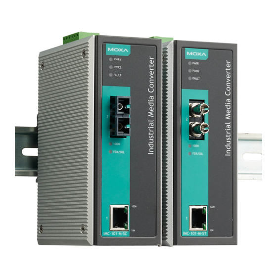
Overview Moxa’s IMC-101 industrial media converters are specially designed for reliable and stable operation in harsh industrial environments and provide industrial-grade media conversion between 10/100BaseT(X) and 100BaseFX. The IMC-101 comes with a relay output warning alarm to help prevent damages and losses, and its reliable industrial design is excellent for keeping your industrial automation applications running continuously. - Page 3 Panel Layout of IMC-101 Series 1. Grounding screw 2. Terminal block for power input PWR1/PWR2 and relay output 3. Heat dissipation vents 4. Dip switch 5. Power input PWR1 LED 6. Power input PWR2 LED 7. Fault LED 8. 100BaseFX (ST connector) Port 9.
-
Page 4: Mounting Dimensions
Mounting Dimensions - 4 -... -
Page 5: Din Rail Mounting
DIN Rail Mounting The aluminum DIN rail attachment plate should be fixed to the back panel of the IMC-101 when you take it out of the box. If you need to reattach the DIN rail attachment plate to the IMC-101, make sure the stiff metal spring is situated towards the top, as shown in the figures below. -
Page 6: Atex And Iecex Information
STEP 3: Once the screws are fixed in the wall, insert the four screw heads through the large parts of the keyhole-shaped apertures, and then slide Moxa Industrial Media Converter downwards, as indicated below. Tighten the four screws for added stability. ATEX and IECEx Information 1. - Page 7 WARNING This equipment has been evaluated as EEx nC IIC T4 equipment under DEMKO Certificate No. 03 ATEX 0324537U. Each module is marked with II 3G and is suitable for use in Zone 2 Explosive Atmospheres. Devices must be installed in a minimum IP54 enclosure as defined in IEC 60529 and EN 60529.
-
Page 8: Wiring The Alarm Contact
ATTENTION This product is intended to be mounted to a well-grounded mounting surface such as a metal panel. Wiring the Alarm Contact The alarm contact is made up of the two middle contacts of the terminal block on the IMC-101’s top panel. Refer to the next section for detailed instructions on how to connect the wires to the terminal block connector, and how to attach the terminal block connector to the terminal block receptor. -
Page 9: 10/100Baset(X) Ethernet Port Connection
10/100BaseT(X) Ethernet Port Connection The 10/100BaseT(X) ports located on the IMC-101’s front panel are used to connect to Ethernet-enabled devices. Below we show pinouts for both MDI (NIC-type) ports and MDI-X (HUB/Switch-type) ports, and also show cable wiring diagrams for straight-through and cross-over Ethernet cables. -
Page 10: Redundant Power Inputs
SC-Port Pinouts SC-Port to SC-Port Cable Wiring ST-Port Pinouts ST-Port to ST-Port Cable Wiring ATTENTION This is a Class 1 Laser/LED product. Do not stare into the laser beam. Redundant Power Inputs Both power inputs can be connected simultaneously to live DC power sources. -
Page 11: Dip Switch Setting
Dip Switch Setting Dip Switch 1 (Default: Off) ON: Enables the PORT Alarm. If the port’s link fails, the relay will form an open circuit and the fault LED will light up. Off: Disables the corresponding PORT Alarm. The relay will form a closed circuit and the Fault LED will never light up. -
Page 12: Auto Mdi/Mdi-X Connection
Auto MDI/MDI-X Connection The Auto MDI/MDI-X function allows users to connect the IMC-101’s 10/100BaseTX ports to any kind of Ethernet device, without paying attention to the type of Ethernet cable being used for the connection. This means that you can use either a straight-through cable or cross-over cable to connect the IMC-101 to Ethernet devices. -
Page 13: Power Requirements
Optical Fiber Multi Single Single mode mode, 40 mode, 80 Distance, km Wavelength, nm 1300 1310 1550 Min. TX Output, dBm Max. TX Output, dBm Sensitivity, dBm Recommended Diameter 62.5/125 9/125 9/125 (Core/Cladding) μm (1 dB/km, 800 MHz x km) Power Requirements Input Voltage 24 VDC (12 to 45 VDC);... -
Page 14: Product Category
Serial Number The serial number of a product is made up of 12 alphanumeric characters and includes the region in which the product was manufactured, the year and month the product was manufactured, the product category, and the production number. Position Meaning Possible...
Need help?
Do you have a question about the IMC-101 Series and is the answer not in the manual?
Questions and answers