Table of Contents
Advertisement
Advertisement
Table of Contents

Related Manuals for Moxa Technologies IMC-P101 Series


Summary of Contents for Moxa Technologies IMC-P101 Series
- Page 1 Moxa PoE Media Converter IMC-P101 Hardware Installation Guide First Edition, November 2009 © 2009 Moxa Inc. All rights reserved. Reproduction without permission is prohibited. Fl.4, No.135, Lane 235, Pao-Chiao Rd. Shing Tien City, Taipei, Taiwan, R.O.C. TEL: +886-2-8919-1230 P/N: 1802001015010...
- Page 2 Ethernet media conversion from 10/100 BaseT(X) to 100 BaseFX(SC/ST connectors). These media converters are classified as power source equipment (PSE), and when used in this way, the IMC-P101 series provides up to 15.4 watts to powered devices (PD). The IMC-P101 series can be used to power IEEE 802.3af compliant powered devices (PD), eliminating the need for...
-
Page 3: Package Checklist
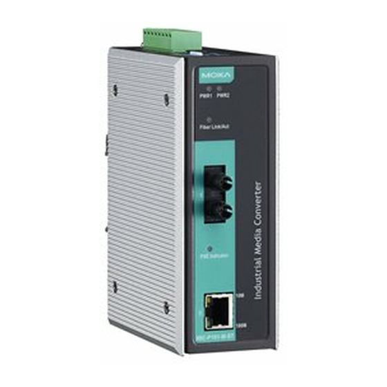
Package Checklist Moxa PoE Media Converter is shipped with the following items. If any of these items is missing or damaged, please contact your customer service representative for assistance. IMC-P101 series media converter. Hardware Installation Guide (printed). Warranty Card. Features 10/100BaseT(X) Auto-Negotiation and Auto-MDI/MDI-X. - Page 4 Panel Layout of the IMC-P101 Series Top Panel View Grounding screw Terminal block for power input PWR1/PWR2 Heat dissipation vents and relay output DIP switch Power input PWR1 LED Power input PWR2 LED Front Panel View (IMC-P101-M-ST) Fiber Link/Active LED...
-
Page 5: Mounting Dimensions
Mounting Dimensions 42.4 mm 40 mm (1.67 in) (1.57 in) IMC-P101-M-SC 51.65 mm 12.06 mm 101.4 mm (3.99 in) (2.03 in) (0.47 in) 110.2 mm (4.34 in) Side View Front View 30.5 mm (1.2 in) 34 mm (1.34 in) 51.6 mm (2.03 in) -
Page 6: Din-Rail Mounting
DIN-Rail Mounting The aluminum DIN-Rail attachment plate should be fixed to the back panel of the IMC when you take it out of the box. If you need to reattach the DIN-Rail attachment plate to the IMC, make sure the stiff metal spring is situated towards the top, as shown in the figures below. - Page 7 STEP 2: Mounting the Moxa PoE Media Converter on the wall requires 4 screws. Use the IMC, with wall mount plates attached, as a guide to mark the correct locations of the 4 screws. The heads of the screws should be less than 6.0 mm in diameter, and the shafts should be less than 3.5 6.0 mm mm in diameter, as shown in the figure at the right.
-
Page 8: Wiring The Redundant Power Inputs
Before connecting the IMC to DC power inputs, make sure the DC power source voltage is stable. Communication Connections IMC-P101 models have one 10/100BaseT(X) Ethernet port, and one 100BaseFX (SC or ST type connector) fiber port. 10/100BaseT(X) Ethernet Port Connection The 10/100BaseT(X) Ethernet port located on the IMC’s front panel is used to... -
Page 9: 100Basefx Ethernet Port Connection
RJ45 (8-pin) to RJ45 (8-pin) Straight-Through Cable Wiring Straight-Through Cable Switch Port NIC Port RJ45 Plug Pin 1 RJ45 RJ45 Connector Cable Wiring Connector RJ45 (8-pin) to RJ45 (8-pin) Cross-Over Cable Wiring Cross-Over Cable Switch Port Switch Port (NIC Port) (NIC Port) RJ45 Plug Pin 1 RJ45... -
Page 10: Redundant Power Inputs
Cable Wiring ATTENTION This is a Class 1 Laser/LED product. Do not stare into the Laser Beam. Redundant Power Inputs Both power inputs can be connected simultaneously to live DC power sources. If one power source fails, the other live source acts as a backup, and automatically supplies all of the Moxa Industrial Media Converter’s power needs. -
Page 11: Led Indicators
100 Mbps, which is equivalent to full duplex mode. Disable Enable* PSE: Power Source Equipment. “ON”: Disables “PSE”, IMC-P101 series do NOT provide power to PD (Powered Device). “OFF”: Enables “PSE”, IMC-P101 series provides power to PD (Powered Device). -
Page 12: Specifications
5 Flash Power overload Fault 9 Flash Power Management Allocation Exceeded Ethernet port 10 Mbps link is active. Yellow Blinking Data is being transmitted at 10 Mbps. Ethernet port 10 Mbps link is inactive. Ethernet port 100 Mbps link is active. 100M Green Blinking Data is being transmitted at 100 Mbps. - Page 13 a. 50/125 μm, 800 MHz*km fiber optic cable b. 62.5/125 μm, 500 MHz*km fiber optic cable c. 9/125 μm, 3.5 PS/(nm*km) fiber optic cable Physical Characteristics Housing Metal Dimensions (W x H x D) 144.45 x 110.2 x 51.65 mm (5.69 x 4.34 x 2.03 Weight Product only: 525g Packaged: 710g...
- Page 14 Technical Support Contact Information www.moxa.com/support Moxa Americas: Moxa China (Shanghai office): Toll-free: 1-888-669-2872 Toll-free: 800-820-5036 Tel: +1-714-528-6777 Tel: +86-21-5258-9955 Fax: +1-714-528-6778 Fax: +86-10-6872-3958 Moxa Europe: Moxa Asia-Pacific: Tel: +49-89-3 70 03 99-0 Tel: +886-2-8919-1230 Fax: +49-89-3 70 03 99-99 Fax: +886-2-8919-1231 - 14 -...
Need help?
Do you have a question about the IMC-P101 Series and is the answer not in the manual?
Questions and answers