Moxa Technologies IMC-101 Hardware Installation Manual
Industrial media converter
Hide thumbs
Also See for IMC-101:
- Hardware installation manual (15 pages) ,
- Hardware installation manual (15 pages)

Subscribe to Our Youtube Channel
Related Manuals for Moxa Technologies IMC-101


Summary of Contents for Moxa Technologies IMC-101
- Page 1 MOXA Industrial Media Converter IMC-101 Hardware Installation Guide Third Edition, July 2004...
-
Page 3: Package Checklist
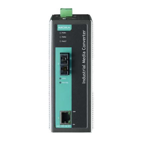
This product has a wide operating temperature range, from -40 to 75°C, and are designed to withstand a high degree of vibration and shock. The rugged hardware design makes IMC-101 perfect for ensuring that your Ethernet equipment can withstand critical industrial applications, such as in hazardous locations (Class 1 Division 2/Zone 2), and complies with FCC, TÜV, UL, and CE Standards... - Page 4 Panel Layout of IMC-101 series Grounding screw Terminal block for power input P1/P2 and relay output Heat dissipation orifices Dip switch Power input P1 LED Power input P2 LED Fault LED 100BaseFX (ST connector) Port FX port’s 100 Mbps LED FX port’s Full Duplex/Collision...
-
Page 5: Mounting Dimensions
Mounting Dimensions DIN-Rail Mounting The aluminum DIN-Rail attachment plate should be fixed to the back panel of IMC when you take it out of the box. If you need to reattach the DIN-Rail attachment plate to IMC, make sure the stiff metal spring is situated towards the top, as shown in the figures below —... -
Page 6: Wall Mounting (Optional)
STEP 1: STEP 2: Insert the top of the DIN-Rail into the The DIN-Rail attachment unit will slot just below the stiff metal spring. snap into place as shown below. To remove MOXA Industrial Media Converter from the DIN-Rail, simply reverse Steps 1 and 2 above. -
Page 7: Wiring Requirements
STEP 3: Once the screws are fixed in the wall, insert the four screw heads through the large parts of the keyhole-shaped apertures, and then slide MOXA Industrial Media Converter downwards, as indicated below. Tighten the four screws for added stability. ⇒... - Page 8 Safety First! Be sure to disconnect the power cord before installing and/or wiring your MOXA Industrial Media Converter. Safety First! Calculate the maximum possible current in each power wire and common wire. Observe all electrical codes dictating the maximum current allowable for each wire size. If the current goes above the maximum ratings, the wiring could overheat, causing serious damage to your equipment.
-
Page 9: Wiring The Redundant Power Inputs
FAULT: The two middle contacts of the 6-contact terminal block connector are used to detect both power faults and port faults. The two wires attached to the Fault contacts form an open circuit when: 1. IMC has lost power from one of the DC power inputs. -
Page 10: Communication Connections
Communication Connections IMC-101 models have one 10/100BaseT(X) Ethernet port, and one 100BaseFX (SC or ST type connector) fiber port. 10/100BaseT(X) Ethernet Port Connection The 10/100BaseT(X) ports located on IMC’s front panel are used to connect to Ethernet-enabled devices. Below we show pinouts for both MDI (NIC-type) ports and MDI-X (HUB/Switch-type) ports, and also show cable wiring diagrams for straight-through and cross-over Ethernet cables. -
Page 11: Redundant Power Inputs
SC-Port Pinouts SC-Port to SC-Port Cable Wiring ST-Port Pinouts ST-Port to ST-Port Cable Wiring This is Class 1 Laser/LED product. Do not stare into the Laser Beam. Redundant Power Inputs Both power inputs can be connected simultaneously to live DC power sources. -
Page 12: Dip Switch Setting
Dip Switch Setting IMC-101 series DIP switch Dip Switch 1 (Default: Off ) ON: Enables the PORT Alarm. If the port’s link fails, the relay will form an open circuit and the fault LED will light up. Off: Disables the corresponding PORT Alarm. The relay will form a closed circuit and the Fault LED will never light up. -
Page 13: Auto Mdi/Mdi-X Connection
100BaseTX Port’s link is inactive FX port’s 100 Mbps is active 100M Data is being transmitted at 100 GREEN Blinking (FX) Mbps 100BaseFX port is inactive 100BaseFX port is being transmitted at full duplex FDX/COL GREEN Collision occurs Blinking 100BaseFX port is being transmitted at half duplex Auto MDI/MDI-X Connection The Auto MDI/MDI-X function allows users to connect MOXA Industrial... -
Page 14: Specifications
2 km Wavelength 1310 nm Min. TX Output -20 dBm (IMC101-M), -15 dBm (IMC101-S) Max. TX Output -14 dBm (IMC-101-M), -6 dBm (IMC-101-S) Sensitivity -36 to -32 dBm (IMC101-M), -34 to -32 dBm (IMC101-S) Power Input Voltage 12 to 48 VDC; Redundant inputs Input Current (@24V) 0.2 A... -
Page 15: Environmental Type Tests
EN61000-4-4 (EFT), level 3 EN61000-4-5 (Surge), level 3 EN61000-4-2 (CS), level 3 Shock IEC 60068-2-27 Free Fall IEC 60068-2-32 Vibration IEC 60068-2-6 WARRANTY 5 years EMS Type Tests Severity Test Description Test Levels Levels +/- 8 KV discharge Contact +/- 6 KV discharge 61000-4-2 contact... -
Page 16: Moxa Internet Services
MOXA Internet Services Customer satisfaction is our number one concern, and to ensure that customers receive the full benefit of our products, Moxa Internet Services has been set up to provide technical support, driver updates, product information, and user’s manual updates. -
Page 17: Revision History
Revision History Document Revision Date Revision Details Edition June 15, 2004 Updated the edition of this manual on the title page. Changed the Moxa logo on the title page. Added several “Attention” messages Added one product feature: Operating temperature ranges from 0 to 60°C, or extended operting temperature from –40 to 75°C for (-T) models.
Need help?
Do you have a question about the IMC-101 and is the answer not in the manual?
Questions and answers