Table of Contents
Advertisement
Quick Links
Quick Installation Guide
Moxa Americas:
Toll-free: 1-888-669-2872
Tel:
1-714-528-6777
Fax:
1-714-528-6778
Moxa Europe:
Tel:
+49-89-3 70 03 99-0
Fax:
+49-89-3 70 03 99-99
Moxa India:
Tel:
+91-80-4172-9088
Fax:
+91-80-4132-1045
IMC-P101
Moxa PoE Media Converter
Edition 3.0, August 2016
Technical Support Contact Information
www.moxa.com/support
2016 Moxa Inc. All rights reserved.
Moxa China (Shanghai office):
Toll-free: 800-820-5036
Tel:
+86-21-5258-9955
Fax:
+86-21-5258-5505
Moxa Asia-Pacific:
Tel:
+886-2-8919-1230
Fax:
+886-2-8919-1231
P/N: 1802001015012
*1802001015012*
Advertisement
Table of Contents

Related Manuals for Moxa Technologies IMC-P101 Series


Summary of Contents for Moxa Technologies IMC-P101 Series
- Page 1 IMC-P101 Quick Installation Guide Moxa PoE Media Converter Edition 3.0, August 2016 Technical Support Contact Information www.moxa.com/support Moxa Americas: Moxa China (Shanghai office): Toll-free: 1-888-669-2872 Toll-free: 800-820-5036 Tel: 1-714-528-6777 Tel: +86-21-5258-9955 Fax: 1-714-528-6778 Fax: +86-21-5258-5505 Moxa Europe: Moxa Asia-Pacific: Tel: +49-89-3 70 03 99-0 Tel: +886-2-8919-1230...
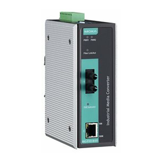
- Page 2 Overview The IMC-P101 series is an Ethernet to fiber optic media converter. It provides Ethernet media conversion from 10/100 BaseT(X) to 100 BaseFX(SC/ST connectors). These media converters are classified as power source equipment (PSE), and when used in this way, the IMC-P101 series provides up to 15.4 watts to powered devices (PD).
-
Page 3: Package Checklist
Moxa PoE Media Converter is shipped with the following items. If any of these items is missing or damaged, please contact your customer service representative for assistance. • IMC-P101 series media converter. • Quick Installation Guide (printed). • Warranty Card. - Page 4 Panel Layout of the IMC-P101 Series 1. Grounding screw 2. Terminal block for power input PWR1/PWR2 3. Heat dissipation vents and relay output 4. DIP switch 5. Power input PWR1 LED 6. Power input PWR2 LED 7. Fiber Link/Active LED 8.
-
Page 5: Mounting Dimensions
Mounting Dimensions - 5 -... -
Page 6: Din-Rail Mounting
DIN-Rail Mounting The aluminum DIN-Rail attachment plate should be fixed to the back panel of the IMC when you take it out of the box. If you need to reattach the DIN-Rail attachment plate to the IMC, make sure the stiff metal spring is situated towards the top, as shown in the figures below. -
Page 7: Wiring The Redundant Power Inputs
STEP 3: Once the screws are fixed in the wall, insert the four screw heads through the large openings of the keyhole-shaped apertures, and then slide Moxa PoE Media Converter downwards, as indicated below. Tighten the four screws for added stability. -
Page 8: 10/100Baset(X) Ethernet Port Connection
10/100BaseT(X) Ethernet Port Connection The 10/100BaseT(X) Ethernet port located on the IMC’s front panel is used to connect to Ethernet-enabled devices. Illustrated below are pinouts for both MDI (NIC-type) ports and MDI-X (HUB/Switch-type) ports, and also cable wiring diagrams for straight-through and cross-over Ethernet cables. -
Page 9: Redundant Power Inputs
SC-Port Pinouts SC-Port to SC-Port Cable Wiring ST-Port Pinouts ST-Port to ST-Port Cable Wiring ATTENTION This is a Class 1 Laser/LED product. Do not stare into the Laser Beam. Redundant Power Inputs Both power inputs can be connected simultaneously to live DC power sources. -
Page 10: Led Indicators
100 Mbps, which is equivalent to full duplex mode. Disable Enable* PSE: Power Source Equipment. “ON”: Disables “PSE”, IMC-P101 series do NOT provide power to PD (Powered Device). “OFF”: Enables “PSE”, IMC-P101 series provides power to PD (Powered Device). P.R.R. Enable Disable* P.R.R.: Power Remote Reset... -
Page 11: Specifications
Color State Description PSE is enabled. 1 Flash Low Signature Resistance 2 Flash High Signature Resistance Green Indicator 5 Flash Power overload Fault Power Management Allocation 9 Flash Exceeded Ethernet port 10 Mbps link is active. Yellow Blinking Data is being transmitted at 10 Mbps. Ethernet port 10 Mbps link is inactive. - Page 12 Physical Characteristics Housing Metal Dimensions (W x H x D) 144.45 x 110.2 x 51.65 mm (5.69 x 4.34 x 2.03 in) Weight Product only: 525g Packaged: 710g Installation DIN-Rail mounting, Wall Mounting (optional kit) Environmental Limits Operating Temperature Standard Models: 0 to 60°C (32 to 140°F) Wide Temp.
Need help?
Do you have a question about the IMC-P101 Series and is the answer not in the manual?
Questions and answers