Table of Contents
Advertisement
Quick Installation Guide
Moxa Industrial Media Converter
Moxa Americas:
Toll-free: 1-888-669-2872
Tel:
1-714-528-6777
Fax:
1-714-528-6778
Moxa Europe:
Tel:
+49-89-3 70 03 99-0
Fax:
+49-89-3 70 03 99-99
Moxa India:
Tel:
+91-80-4172-9088
Fax:
+91-80-4132-1045
IMC-101G Series
Edition 7.0, February 2017
Technical Support Contact Information
www.moxa.com/support
2017 Moxa Inc. All rights reserved.
Moxa China (Shanghai office):
Toll-free: 800-820-5036
Tel:
+86-21-5258-9955
Fax:
+86-21-5258-5505
Moxa Asia-Pacific:
Tel:
+886-2-8919-1230
Fax:
+886-2-8919-1231
P/N: 1802001014017
*1802001014017*
Advertisement
Table of Contents

Related Manuals for Moxa Technologies IMC-101G Series


Summary of Contents for Moxa Technologies IMC-101G Series
- Page 1 IMC-101G Series Quick Installation Guide Moxa Industrial Media Converter Edition 7.0, February 2017 Technical Support Contact Information www.moxa.com/support Moxa Americas: Moxa China (Shanghai office): Toll-free: 1-888-669-2872 Toll-free: 800-820-5036 Tel: 1-714-528-6777 Tel: +86-21-5258-9955 Fax: 1-714-528-6778 Fax: +86-21-5258-5505 Moxa Europe: Moxa Asia-Pacific:...
-
Page 2: Package Checklist
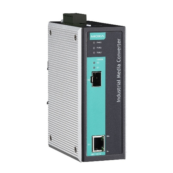
Overview Moxa’s IMC-101G industrial gigabit media converter is designed for reliable and stable operations in harsh industrial environments, and it provides industrial-grade media conversion between 10/100/1000BaseT(X) and 1000BaseSX/LSX/LX/LH/LHX/ZX/EZX (SFP Slot) connections. The IMC-101G’s reliable industrial design is excellent for keeping your industrial automation applications running continuously, and it comes with an alarm that activates a relay output to help prevent damage. - Page 3 Panel Layouts of the IMC-101G Series Grounding screw Terminal block for power inputs (PWR1/PWR2) and relay output Heat dissipation vents Dip switches Power input PWR1 LED Power input PWR2 LED Fault LED SFP port’s 1000 Mpbs G2 LED TP port’s 1000 Mpbs G1 LED 10.
-
Page 4: Din-Rail Mounting
Dimensions; unit = mm (inch) DIN-Rail Mounting The aluminum DIN-rail attachment plate should be fixed to the back panel of the IMC-101G when you take it out of the box. If you need to reattach the DIN-rail attachment plate to the IMC-101G, make sure the stiff metal spring is situated towards the top, as shown in the figures below. -
Page 5: Wall Mounting (Optional)
Wall Mounting (Optional) For some applications, you will find it convenient to mount the IMC-101G on the wall, as illustrated below. STEP 1: Remove the aluminum DIN-rail attachment plate from the IMC-101G and then attach the wall-mount plates, as shown in the diagrams below. -
Page 6: Atex And Iecex Information
ATEX and IECEx Information 1. Certification number DEMKO 09 ATEX0812123X IECEx: IECEx UL 13.0046X 2. Ambient range: II 3G (-40°C ≤ T ≤ 75°C) DEMKO 3. Certification string 09 ATEX 0812123X ATEX: Ex nA nC IIC T4 Gc Ex nA nC IIC T4 Gc -40°C ≦... - Page 7 ATTENTION Safety First! Calculate the maximum possible current in each power wire and common wire. Observe all electrical codes dictating the maximum allowed current for each wire size. If the current goes above the allowed maximum, the wiring could overheat, causing serious damage to your equipment.
-
Page 8: Wiring The Alarm Contact
Wiring the Alarm Contact The Alarm Contact is made up of the two middle contacts of the terminal block on the IMC-101G’s top panel. Refer to the next section for detailed instructions on how to connect the wires to the terminal block connector and how to attach the terminal block connector to the terminal block receptor. -
Page 9: Communication Connections
Communication Connections All IMC-101G models have one 10/100/1000BaseT(X) Ethernet port and one 1000Base SFP fiber port. 10/100/1000BaseT(X) Ethernet Port Connection The 10/100/1000BaseT(X) ports located on the IMC-101G’s front panel are used to connect to Ethernet-enabled devices. Below we show pinouts for both MDI (NIC-type) ports and MDI-X (HUB/switch-type) ports, and also show cable wiring diagrams for straight-through and crossover Ethernet cables. -
Page 10: Redundant Power Inputs
1000BaseT(X) Ethernet Port Connection 1000BaseT(X) data is transmitted on differential TRD+/- signal pairs over copper wires. MDI/MDI-X Port Pinouts Signal TRD (0) + TRD (0) - TRD (1) + TRD (2) + TRD (2) - TRD (1) - TRD (3) + TRD (3) - 1000BaseSFP Fiber Port The gigabit Ethernet ports on the IMC-101G are 1000BaseSFP fiber ports,... -
Page 11: Alarm Contact
Alarm Contact The IMC-101G has one alarm contact located on the top panel. For detailed instructions on how to connect the alarm contact power wires to the two middle contacts of the 6-contact terminal block connector, see the “Wiring the Alarm Contact” section above. A typical scenario would be to connect the fault circuit to a warning light located in the control room. -
Page 12: Led Indicators
LED Indicators The front panel of the IMC-101G has several LED indicators. The function of each LED is described in the table below. Color State Description Power is being supplied to power input PWR1 PWR1 Amber Power is not being supplied to power input PWR1 Power is being supplied to power input PWR2 PWR2 Amber Power is not being supplied to power input PWR2... -
Page 13: Specifications
Auto-negotiation takes place when an RJ45 cable connection is made. Each time a LINK is enabled, the IMC-101G advertises its capability for using 10 Mbps, 100 Mbps, or 1000 Mbps transmission speeds, with the device at the other end of the cable expected to advertise similarly. Depending on what type of device is connected, this will result in agreement to operate at a speed of 10 Mbps, 100 Mbps, or 1000 Mbps. - Page 14 NOTE The actual communication distance depends on many factors, including connector loss, cable deployment, and the age of the cabling system. We recommend doing a link budget analysis and reserving a 3 dB margin for such factors. NOTE Please refer to the SFP-1G Series datasheet for more detailed SFP module specifications.
Need help?
Do you have a question about the IMC-101G Series and is the answer not in the manual?
Questions and answers