Table of Contents
Advertisement
Quick Links
Quick Installation Guide
Moxa Industrial Media Converter
Moxa Americas:
Toll-free: 1-888-669-2872
Tel:
1-714-528-6777
Fax:
1-714-528-6778
Moxa Europe:
Tel:
+49-89-3 70 03 99-0
Fax:
+49-89-3 70 03 99-99
Moxa India:
Tel:
+91-80-4172-9088
Fax:
+91-80-4132-1045
IMC-21
Edition 5.0, February 2017
Technical Support Contact Information
www.moxa.com/support
2017 Moxa Inc. All rights reserved.
Moxa China (Shanghai office):
Toll-free: 800-820-5036
Tel:
+86-21-5258-9955
Fax:
+86-21-5258-5505
Moxa Asia-Pacific:
Tel:
+886-2-8919-1230
Fax:
+886-2-8919-1231
P/N: 1802000210014
*1802000210014*
Advertisement
Table of Contents

Related Manuals for Moxa Technologies IMC-21


Summary of Contents for Moxa Technologies IMC-21
- Page 1 IMC-21 Quick Installation Guide Moxa Industrial Media Converter Edition 5.0, February 2017 Technical Support Contact Information www.moxa.com/support Moxa Americas: Moxa China (Shanghai office): Toll-free: 1-888-669-2872 Toll-free: 800-820-5036 Tel: 1-714-528-6777 Tel: +86-21-5258-9955 Fax: 1-714-528-6778 Fax: +86-21-5258-5505 Moxa Europe: Moxa Asia-Pacific: Tel:...
-
Page 2: Package Checklist
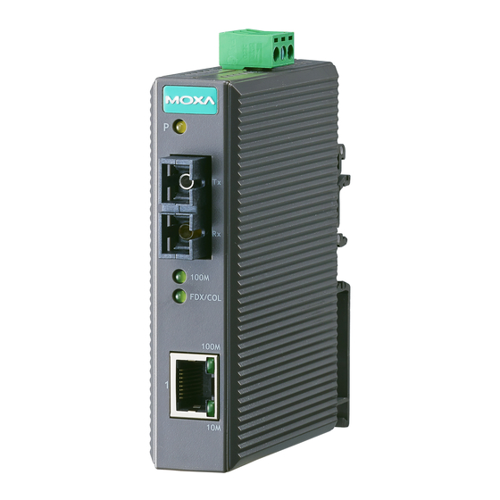
IMC-21 accepts either a 12 to 48 VDC power input. It operates reliably in a temperature range from -10 to 60°C, and IMC-21’s rugged hardware design makes it ideal for demanding industrial applications, such as those that comply with FCC, CE. - Page 3 Panel Layout of IMC-21 Series 1. Heat dissipation orifices 2. Terminal block for power input and grounding 3. DIP switch 4. Moxa Logo 5. Power input LED 6. 100BaseFX (SC/ST connector) port 7. FX port’s 100 Mbps LED 8. FX port’s FDX/COL LED 9.
-
Page 4: Mounting Dimensions
To remove Moxa IMC-21 from the DIN-Rail, insert a flat-blade screw driver horizontally into the DIN-Rail kit under the IMC-21, and then pull it upwards and release IMC towards you away from the DIN-Rail. - 4 -... -
Page 5: Wiring Requirements
Wiring Requirements ATTENTION Safety First! Be sure to disconnect the power cord before installing and/or wiring your Moxa Industrial Media Converter. Calculate the maximum possible current in each power wire and common wire. Observe all electrical codes dictating the maximum current allowable for each wire size. If the current goes above the maximum rating, the wiring could overheat, causing serious damage to your equipment. -
Page 6: Wiring The Power Inputs
IMC’s top panel. Front View Communication Connections IMC-21 has one 10/100BaseT(X) Ethernet port. RJ45 Ethernet Port Connection The 10/100BaseT(X) port located on IMC’s front panel are used to connect to Ethernet-enabled devices. - Page 7 RJ45 (8-pin) to RJ45 (8-pin) Cross-Over Cable Wiring Fiber Optical Port Connection The concept behind the SC/ST port and cable is quite straightforward. Suppose you are connecting devices I and II. Contrary to electrical signals, optical signals do not require a circuit in order to transmit data. Consequently, one of the optical lines is used to transmit data from device I to device II, and the other optical line is used transmit data from device II to device I, for full-duplex transmission.
-
Page 8: Dip Switch Settings
FORCE: Force TP port into 10M or half duplex mode After changing the DIP switch setting, you will need to power off and then power on the IMC-21 to activate the new setting. LED Indicators The front panel of Moxa Industrial Media Converter contains several LED indicators. -
Page 9: Auto Mdi/Mdi-X Connection
LFP DIP switch is set to “LFP” mode: Device1 DUTA TP DUTA FO DUTB FO DUTB TP Device 2 TP LED LNK LED LNK LED TP LED Faulted F1 Faulted OFF F2 Faulted OFF Faulted LFP DIP switch is set to “DIS” mode: Device1 DUTA TP DUTA FO... -
Page 10: Dual Speed Functionality And Switching
Auto-Negotiation and Speed Sensing Moxa IMC-21 series’ RJ45 Ethernet port supports auto-negotiation in 10BaseT and 100BaseT(X) modes, with operation governed by the IEEE 802.3u standard. This means that some nodes could be operating at 10 Mbps, while at the same time, other nodes are operating at 100 Mbps. -
Page 11: Fcc Warning
Power Input Voltage 12 to 48 VDC M-SC/ST: S-SC: Power Consumption 271 mA @ 12 V 258 mA @ 12 V 137 mA @ 24 V 129 mA @ 24 V 77 mA @ 48 V 71 mA @ 48 V Connection Removable 3-contact Terminal Block Overload Current...
Need help?
Do you have a question about the IMC-21 and is the answer not in the manual?
Questions and answers