
Related Manuals for Moxa Technologies IMC-21GA-T


Summary of Contents for Moxa Technologies IMC-21GA-T
- Page 1 IMC-21GA Hardware Installation Guide Moxa Industrial Media Converter Second Edition, October 2014 2014 Moxa Inc. All rights reserved. P/N: 1802000210031...
-
Page 2: Package Checklist
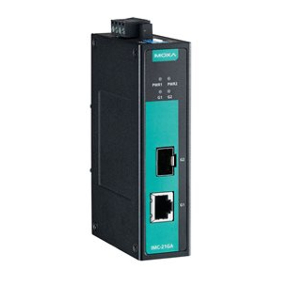
Overview The IMC-21GA series includes industrial 10/100/1000BaseT(X) to 100/1000BaseFX media converters that provide a cost-effective solution, and are specially designed for reliable and stable operation in industrial environments. Package Checklist Moxa’s IMC-21GA is shipped with the following items. If any of these items are missing or damaged, please contact your customer service representative for assistance. -
Page 3: Panel Layout
Panel Layout 1. Shielding Ground 2. Terminal block for power input 3. Dip switch 4. Power LED 5. Gigabit Copper (G1) / Fiber (G2) Port LED 6. SFP module slot 7. 10/100/1000BaseT(X) Port 8. SX/LX Fiber Port, SC connector 9. DIN rail kit - 3 -... -
Page 4: Mounting Dimensions
Mounting Dimensions DIN Rail Mounting The aluminum DIN rail attachment plate should be fixed to the back panel of the IMC-21GA when you take it out of the box. If you need to reattach the DIN rail attachment plate to the IMC-21GA, make sure the stiff metal spring is situated towards the top. -
Page 5: Grounding The Imc-21Ga
• Do not run signal or communications wiring and power wiring in the same wire conduit. To avoid interference, wires with different signal characteristics should be routed separately. • You can use the type of signal transmitted through a wire to determine which wires should be kept separate. -
Page 6: Communication Connections
Communication Connections RJ45 Ethernet Port Connection The IMC-21GA has one 10/100/1000BaseT(X) Ethernet port located on the front panel for connecting to Ethernet-enabled devices. When connected to a 10/100 Mbps Ethernet port, the pinouts and cable wiring diagrams for both MDI (NIC-type) and MDI-X (HUB/switch-type) ports for both straight-through and cross-over Ethernet cables are: MDI Port Pinouts MDI-X Port Pinouts... - Page 7 1000BaseSFP Fiber Port Connection The Gigabit Ethernet ports on the IMC-21GA are 1000BaseSFP Fiber ports, which require using Gigabit mini-GBIC fiber transceivers to work properly. The concept behind the LC port and cable is straightforward. Suppose you are connecting devices I and II; contrary to electrical signals, optical signals do not require a circuit in order to transmit data.
-
Page 8: Dip Switch Settings
ATTENTION The IMC-21GA is only compatible with transceiver modules from Moxa's SFP-1G series and SFP-1FE series. If you are using the SFP-1FESLC-T, SFP-1FELLC-T, or SFP-1FEMLC-T, use version V1.3 or above to ensure that the IMC-21GA's media converter functionality works properly. ATTENTION This is a Class 1 Laser/LED product. -
Page 9: Led Indicators
LED Indicators The front panel of the Moxa IMC-21GA contains several LED indicators. The function of each LED is described in the table below. Color State Description Power is being supplied to power input (V1+, V1-) PWR1 Amber Power is not being supplied to power input (V1+, V1-) Power is being supplied to power input (V2+, V2-) PWR2 Amber... -
Page 10: Auto Mdi/Mdi-X Connection
LFP: DIP switch is set to “DIS” mode DUTA TP DUTB TP Device1 DUTA FO DUTB FO Device 2 LNK (G1) LNK (G1) TP LED (G2) LED (G2) LED TP LED TP1 Faulted F1 Faulted F2 Faulted TP2 Faulted Auto MDI/MDI-X Connection The Auto MDI/MDI-X function allows users to connect the Moxa IMC-21GA’s 10/100/1000BaseT(X) ports to any kind of Ethernet device, regardless of the type of Ethernet cable used for the connection. -
Page 11: Federal Communications Commission Statement
DIP Switch The following are DIP switch selectable: Fiber port’s connection speed (FX Speed), Energy Efficient Ethernet (EEE), Link Fault Pass Through (LFP) Fiber Optics Multi mode Single mode (IMC-21GA-SX-SC) (IMC-21GA-LX-SC) Distance, km Wavelength, nm 1310 Min. Tx Output, dBm Max. -
Page 12: Fcc Warning
FCC WARNING This equipment has been tested and found to comply with the limits for a Class A digital device, pursuant to part 15 of the FCC Rules. These limits are designed to provide reasonable protection against harmful interference when the equipment is operated in a commercial environment.
Need help?
Do you have a question about the IMC-21GA-T and is the answer not in the manual?
Questions and answers