
Related Manuals for Moxa Technologies ICF-1171I Series


Summary of Contents for Moxa Technologies ICF-1171I Series
- Page 1 ICF-1171I Series Quick Installation Guide Version 1.0, June 2022 Technical Support Contact Information www.moxa.com/support 2022 Moxa Inc. All rights reserved. P/N: 1802011710010 *1802011710010*...
- Page 2 CAN system works uninterrupted. The ICF-1171I Series can separate and protect critical segments of the system from the rest of the CAN network and is protocol independent, allowing it to work with all the different CAN protocols and frame lengths.
-
Page 3: Package Checklist
Supports higher layer CAN protocols such as CANopen, DeviceNet, SAE J1939, etc. • Supports point-to-point connection to another ICF-1171I Package Checklist Before installing the ICF-1171I Series, verify the package contains the following items: • ICF-1171I Series CAN-to-fiber converter with a DIN-rail kit pre- locked on it •... -
Page 4: Mounting Dimensions
Mounting Dimensions ICF-1171I-S-ST/ICF-1171I-M-ST The appearance is the same for all, including wide-temperature (-T) models; the only difference is the label of the model. Top View Front View - 4 -... -
Page 5: Hardware Installation Procedure
Insert the top of the DIN-rail into The DIN-rail attachment unit will the slot just below the stiff metal snap into place as shown below spring. To remove the ICF-1171I Series from the DIN rail, simply reverse steps 1 and 2 above. - 5 -... -
Page 6: Wall Mounting Installation
Wall-mounting Installation For wall mounting, the suggested direction of the product is upright— the same as for DIN-rail mounting. The following figure illustrates how to attach the screws to the mounting kits: DIN Rail: Wall-mount: - 6 -... -
Page 7: Can Pin Assignment
The ICF-1171I supports dual power inputs for redundancy. When one power input fails, the relay will be triggered. Be sure to install the dual power inputs for the ICF-1171I Series and choose the correct relay output when connecting the alarm. -
Page 8: Fiber Cable
Make sure CAN high (CAN_H) is connected to the CAN high pin, and CAN low (CAN_L) is connected to the CAN low pin of your CAN device. Fiber Cable ST-Port Pinouts ST-Port to ST-Port Cable Wiring ATTENTION This is a Class 1 laser/LED product. Do not stare into the laser beam. - Page 9 Disable OFF (default) There are two rotary switches at the bottom of the ICF-1171I Series, which is used to configure the arbitration rate or data rate of the CAN bus. Rotary switch 1 is used to set up the arbitration rate of CAN (CAN 2.0)/CAN FD (ISO CAN FD);...
-
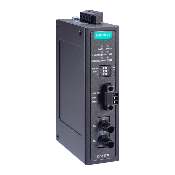
Page 10: Led Indicators
800 kbps 500 kbps 250 kbps Reserved Reserved LED Indicators There are 6 LEDs on the front panel of the ICF-1171I. Color Description PWR1 Green Steady ON: Power is being supplied to PWR1 Off: Power is NOT being supplied to PWR1, or another type of other power error PWR2 Green... - Page 11 Color Description The Bus-Off state, or the auto baudrate (Steady) detection is unsuccessful (Bus-Off state: according to the CAN definition, when the transmit error count exceeds 255, a CAN node will enter the Bus-Off state.) When the LED is steady red, the reception/transmission of CAN messages is not possible.
-
Page 12: Specifications
Typical Scenarios Using the ICF-1171I Connecting two CAN or two CAN FD networks Extending Transmission Distances Typically, the total transmission distance of a CAN (CAN 2.0) or CAN FD (ISO CAN FD) system can be extended by 2 km (multi-mode fiber) or by 40 km (single-mode fiber) using ICF-1171I converters. - Page 13 Fiber Communication Connector Type ST (single-mode and multi-mode), 100Base-FX Cable Requirements 9/125 μm (single-mode) or 62.5/125 μm (multi- mode) Wavelength 1310 nm (single-mode and multi-mode) Tx Power > -5 dBm (single-mode) or > -20 dBm (multi- mode) Rx Range -3 to -34 dBm (single-mode), -3 to -32 dBm (multi-mode) Environmental Limits Operating...
Need help?
Do you have a question about the ICF-1171I Series and is the answer not in the manual?
Questions and answers