Advertisement
Quick Links
Chipsmall Limited consists of a professional team with an average of over 10 year of expertise in the distribution
of electronic components. Based in Hongkong, we have already established firm and mutual-benefit business
relationships with customers from,Europe,America and south Asia,supplying obsolete and hard-to-find components
to meet their specific needs.
With the principle of "Quality Parts,Customers Priority,Honest Operation,and Considerate Service",our business
mainly focus on the distribution of electronic components. Line cards we deal with include
Microchip,ALPS,ROHM,Xilinx,Pulse,ON,Everlight and Freescale. Main products comprise
IC,Modules,Potentiometer,IC Socket,Relay,Connector.Our parts cover such applications as commercial,industrial,
and automotives areas.
We are looking forward to setting up business relationship with you and hope to provide you with the best service
and solution. Let us make a better world for our industry!
Contact us
Tel: +86-755-8981 8866 Fax: +86-755-8427 6832
Email & Skype: info@chipsmall.com Web: www.chipsmall.com
Address: A1208, Overseas Decoration Building, #122 Zhenhua RD., Futian, Shenzhen, China
Advertisement

Subscribe to Our Youtube Channel
Related Manuals for red lion PAXC0000


Summary of Contents for red lion PAXC0000
- Page 1 Chipsmall Limited consists of a professional team with an average of over 10 year of expertise in the distribution of electronic components. Based in Hongkong, we have already established firm and mutual-benefit business relationships with customers from,Europe,America and south Asia,supplying obsolete and hard-to-find components to meet their specific needs.
- Page 2 With an RS232 or RS485 The PAX Digital Input Panel Meters offer many features and performance card installed, it is possible to configure the meter using Red Lion’s Crimson capabilities to suit a wide range of industrial applications. Available in three software.
-
Page 3: Table Of Contents
able OnTenTs Ordering Information ....2 Installing Plug-In Cards ....8 General Meter Specifications . -
Page 4: General Meter Specifications
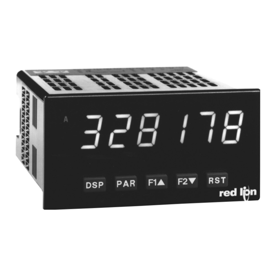
eneral eTer peCifiCaTiOns 1. DISPLAY: 6 digit, 0.56" (14.2 mm) red sunlight readable or standard green ELECTROMAGNETIC COMPATIBILITY Emissions and Immunity to EN 61326:2006: Electrical Equipment for 2. POWER: Measurement, Control and Laboratory use. AC Versions: Immunity to Industrial Locations: AC Power: 85 to 250 VAC, 50/60 Hz, 18 VA Electrostatic discharge EN 61000-4-2... - Page 5 paXC - 1/8 din C Odel OunTer 6-DIGIT LED DISPLAY (Alternating 8 digits for counting) DUAL COUNT QUAD INPUTS UP TO 3 COUNT DISPLAYS SETPOINT ALARM OUTPUTS (W/Plug-in card) PAXC SPECIFICATIONS ANNUNCIATORS: MAXIMUM SIGNAL FREQUENCIES: A - Counter A To determine the maximum frequency for the input(s), first answer the B - Counter B questions with a yes (Y) or no (N).
- Page 6 paXi - 1/8 din C Odel OunTer eTer COUNT, RATE AND SLAVE DISPLAY 6-DIGIT 0.56" RED SUNLIGHT READABLE DISPLAY VARIABLE INTENSITY DISPLAY 10 POINT SCALING (FOR NON-LINEAR PROCESSES) FOUR SETPOINT ALARM OUTPUTS (W/OPTION CARD) RETRANSMITTED ANALOG OUTPUT (W/OPTION CARD) ...
-
Page 7: Optional Plug-In Output Cards
pTiOnal uTpuT ards WARNING: Disconnect all power to the unit before SETPOINT CARDS (PAXCDS) installing Plug-in cards. The PAX and MPAX series has 4 available setpoint alarm output plug-in cards. Only one of these cards can be installed at a time. (Logic state of the outputs can be reversed in the programming.) These plug-in cards include: Adding Option Cards PAXCDS10 - Dual Relay, FORM-C, Normally open &... - Page 8 1.0 i nsTalling The eTer Installation While holding the unit in place, push the panel latch over the rear of the unit The PAX meets NEMA 4X/IP65 requirements when properly installed. The so that the tabs of the panel latch engage in the slots on the case. The panel unit is intended to be mounted into an enclosed panel.
- Page 9 3.0 i nsTalling ards The Plug-in cards are separately purchased optional cards that perform To Install: specific functions. These cards plug into the main circuit board of the meter. The 1. With the case open, locate the Plug-in card connector for the card type to be Plug-in cards have many unique functions when used with the PAX.
-
Page 10: Wiring The Meter
4.0 w iring The eTer WIRING OVERVIEW the noise source frequency is above 1 MHz. c. Connect the shield to common of the meter and leave the other end of the Electrical connections are made via screw-clamp terminals located on the shield unconnected and insulated from earth ground. - Page 11 4.3 INPUT WIRING CAUTION: Sensor input common is NOT isolated from user input common. In order to preserve the safety of the meter application, the sensor input common must be suitably isolated from hazardous live earth referenced voltage; or input common must be at protective earth ground potential. If not, hazardous voltage may be present at the User Inputs and User Input Common terminals.
-
Page 12: Reviewing The Front Buttons And Display
5.0 r eviewing The rOnT uTTOns and isplay Counter 8. 8 . 8 . 8 . 8 . 8 Readout Legends* Setpoint Alarm Annunciators DISPLAY MODE OPERATION PROGRAMMING MODE OPERATION Index display through the selected displays. Quit programming and return to Display Mode Access Programming Mode Store selected parameter and index to next parameter Function key 1;... - Page 13 6.1 mOdule 1 - C a & b i OunT npuT arameTers paXC & i PARAMETER MENU x = Counter A or Counter B Module 1 is the programming for Counter A, Counter B and the Prescaler Output. Counter B parameters follow the Prescaler parameters. For maximum input frequency, the counters should be set to mode NONE and the Prescaler to NO when they are not in use.
- Page 14 PAXI: PRESCALER SCALE VALUE COUNTER B COUNT LOAD VALUE The prescaler output frequency When reset to count load action is selected, Counter B will reset to this value. is the Input A frequency times the prescaler scale value.
- Page 15 6.2 mOdule 2 - u npuT and rOnT anel unCTiOn arameTers PARAMETER MENU Module 2 is the programming for rear terminal user inputs and front panel EXCHANGE PARAMETER LISTS function keys. Three rear terminal user inputs are individually programmable to perform specific meter control functions.
- Page 16 MAINTAINED (LEVEL) RESET AND INHIBIT DEACTIVATE SETPOINT MAINTAINED (LEVEL) The meter deactivates the setpoints configured as , as long as activated The meter performs a reset and inhibits the displays configured as ...
- Page 17 6.3 mOdule 3 - d isplay and rOgram arameTers 3-LOC PARAMETER MENU rAtE SP-n CNtLd SCFAC d-LEV COdE Max Display Counter x Rate Display Counter x Scale Min Display Setpoint 1-4 Display Security Lock-out Display Lock-out Count Load Factor x Lock-out Access Intensity...
- Page 18 6.4 mOdule 4 - r paXr & i npuT arameTers PARAMETER MENU Non-linear Application – Up to 10 Scaling Points Module 4 is the programming for the Rate parameters. For maximum input frequency, Rate assignment should be set to ...
- Page 19 RATE INPUT VALUE FOR SCALING POINT 2 RATE SCALING To scale the Rate, enter a Scaling Display value with a corresponding Scaling Input value. (The Display and Input values can be entered by Key-in or Applied ...
- Page 20 6.5 mOdule 5 - C OunTer npuT arameTers paXC & i PARAMETER MENU Module 5 is the programming for Counter C. For maximum input frequency, COUNTER C DECIMAL POSITION the counter operating mode should be set to when not in use. When set to ...
- Page 21 6.6 mOdule 6 - s eTpOinT larm arameTers 6-SPt PARAMETER MENU SPSEL Lit-n OUt-n SUP-n ACt-n ASN-n SP-n trC-n tYP-n Setpoint Setpoint Output Power-up Setpoint Setpoint Setpoint Setpoint Boundary Select Annunciators Logic State Action Assignment Value Tracking Type Stb-n HYS-n tOFF-n tON-n...
- Page 22 SETPOINT ACTION SETPOINT STANDBY OPERATION : When not using a setpoint, it should be set to (no action). Selecting will disable low acting setpoints at a power up until the display ...
- Page 23 PAXC & I: SETPOINT RESET WITH DISPLAY RESET PAXC & I: SETPOINT RESET WHEN SPn+1 DEACTIVATES Select , so the setpoint output will deactivate (reset) when the Setpoint ...
- Page 24 ), an address is not needed and a value of zero can be used. With multiple ASCII characters or Modbus protocol. Red Lion’s Crimson software can be units (RS485 applications), a unique 2 digit address number must be assigned used for configuring the PAXI (See Ordering Information).
- Page 25 SERIAL MODBUS COMMUNICATIONS 3. If a multiple write includes read only registers, then only the write registers will change. Modbus Communications requires that the Serial Communications Type 4. If the write value exceeds the register limit (see Register Table), then that Parameter (tYPE) be set to Modbus RTU (Mbrtu) or Modbus ASCII (MbASC).
- Page 26 REGISTER FACTORY REGISTER NAME LOW LIMIT HIGH LIMIT ACCESS COMMENTS ADDRESS SETTING 40027 Setpoint 2 Value (Hi word) -199999 999999 Read/Write Active List (A or B) 40028 Setpoint 2 Value (Lo word) 40029 Setpoint 3 Value (Hi word) -199999 999999 Read/Write Active List (A or B) 40030 Setpoint 3 Value (Lo word)
Need help?
Do you have a question about the PAXC0000 and is the answer not in the manual?
Questions and answers