red lion PAXCK Manual

red lion PAXCK Manual

Pax-1/8 din preset timer & real-time clock
Hide thumbs Also See for PAXCK:

Advertisement

Tel +1 (717) 767-6511
Fax +1 (717) 764-0839
www.redlion.net
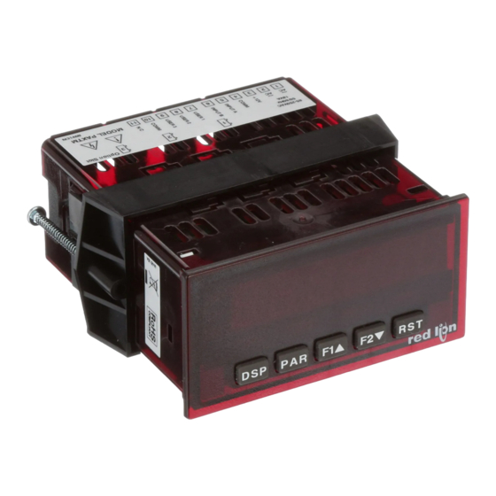
MODEL PAX-1/8 DIN PRESET TIMER (PAXTM) &
U
L
C
US LISTED
US LISTED
4
IND. CONT . EQ.
51EB
GENERAL DESCRIPTION
®
The PAXTM (PAX
Timer) and PAXCK (PAX
features and performance capabilities to suit a wide range of industrial
applications. Both can function as an Elapsed Timer or Preset Timer, while the
PAXCK also offers Real-Time Clock with Date capability. The Plug-in option
cards allow the opportunity to configure the meter for the present application,
while providing easy upgrades for future needs.
Both units can function as an Elapsed Time Indicator. By using two separate
signal inputs and 23 selectable timer ranges, the meters can be programmed to
meet most any timing application. With the addition of a Plug-in Setpoint card,
they can easily become a dual or quad output preset timer.
The PAXCK can also operate as a Real-Time Clock (RTC), with the Real-
Time Clock Card already installed. The meter is capable of displaying time in
12 or 24-hour time formats. The 12-hour format can be displayed in hours and
minutes, with or without an AM/PM indication or in hours, minutes, and
seconds. The 24-hour format can be displayed in hours and minutes or in hours,
minutes, and seconds. The PAXCK is also capable of a calendar display in
which the day, month and/or year can be displayed. The meter will recognize
leap years, and can automatically adjust for Daylight Savings Time. The Real-
Time Clock has the ability to externally synchronize with other PAXCK meters
to provide a uniform display network throughout the plant.
If the application calls for both a Preset Timer and a Real-Time Clock at the
same time, the PAXCK can handle this requirement as well. The meter provides
up to four different displays, accessed via front panel push buttons or external
inputs. The displays are Timer (TMR), which displays the current timer value;
Count (CNT), which displays the current cycle counter value; Date (DAT),
which displays the current programmed date; and Real-Time Clock, which
displays the current time. A battery-backed Real-Time Clock plug-in card is
provided with the PAXCK. This card, which includes a lithium coin-cell battery,
will maintain the time and date when main power is removed.
The meters accept inputs from a variety of sources including switch contacts
and outputs from CMOS or TTL circuits. The input can be configured to trigger
on the edge or level of the incoming pulse. Internal jumpers are available to allow
the selection for sinking inputs (active low) or sourcing inputs (active high).
The front panel keys and three user inputs are programmable to perform
various meter functions. One of the functions includes exchanging parameter
lists, allowing for two separate listings of setpoint values, timer start/stop
values, counter start/stop values and RTC daily on and off values.
DIMENSIONS In inches (mm)
REAL-TIME CLOCK (PAXCK)
®
Clock/Timer) offer many
Note: Recommended minimum clearance (behind the panel) for mounting
clip installation is 2.1" (53.4) H x 5" (127) W.
1
6-DIGIT 0.56" RED SUNLIGHT READABLE DISPLAY
4 SEPARATE DISPLAYS (Timer, Counter, Real-Time Clock, and Date)
CYCLE COUNTING CAPABILITY
PROGRAMMABLE FUNCTION KEYS/USER INPUTS
FOUR SETPOINT ALARM OUTPUTS (W/Plug-in card)
COMMUNICATIONS AND BUS CAPABILITIES (W/Plug-in card)
BUS CAPABILITIES: DEVICENET, MODBUS and PROFIBUS-DP
®
CRIMSON
PROGRAMMING SOFTWARE
NEMA 4X/IP65 SEALED FRONT BEZEL
The meters can have up to four setpoint outputs, determined by the optional
plug-in cards. The setpoint plug-in cards provide dual FORM-C relays (5A),
quad FORM-A relays (3A) or either quad sinking or quad sourcing open
collector logic outputs. The outputs can be assigned to the timer, counter, RTC
date, and RTC time. The outputs can also be independently configured to suit a
variety of control and alarm requirements.
Plug-in cards can also provide serial communications. These include RS232,
RS485, Modbus, DeviceNet, and Profibus-DP. Display values, setpoint alarm
values and setpoint states can be controlled through serial communications.
With the RS232 or RS485 communication card installed, it is possible to
configure the meter using a Windows
data can be saved to a file for later recall.
Once the meters have been initially configured, the parameter list may be
locked out from further modification entirely, or the setpoint, timer start/stop
values, counter start/stop values, RTC time SET, and Display Intensity can be
made accessible. This lockout is possible through a security code or user input.
The meters have been specifically designed for harsh industrial environments.
With a NEMA 4X/IP65 sealed bezel and extensive testing to meet CE
requirements, the meter provides a tough yet reliable application solution.
SAFETY SUMMARY
All safety related regulations, local codes and instructions that appear in this
literature or on equipment must be observed to ensure personal safety and to
prevent damage to either the instrument or equipment connected to it. If
equipment is used in a manner not specified by the manufacturer, the protection
provided by the equipment may be impaired.
Do not use this unit to directly command motors, valves, or other actuators
not equipped with safeguards. To do so can be potentially harmful to persons or
equipment in the event of a fault to the unit.
CAUTION: Risk of Danger.
Read complete instructions prior to
installation and operation of the unit.
Bulletin No. PAXCK-G
Drawing No. LP0524
Released 2/08
®
based program. The meter configuration
CAUTION: Risk of electric shock.

Advertisement

Table of Contents
loading
Need help?

Need help?

Do you have a question about the PAXCK and is the answer not in the manual?

Questions and answers

Subscribe to Our Youtube Channel

Summary of Contents for red lion PAXCK

  • Page 1 The PAXCK can also operate as a Real-Time Clock (RTC), with the Real- Once the meters have been initially configured, the parameter list may be Time Clock Card already installed.
  • Page 2 ABLE ONTENTS Ordering Information ....2 Wiring the Meter ..... . 6 General Meter Specifications.
  • Page 3: Meter Specifications

    Immunity to EN 50082-2 Maximum Count Rate: 50 Hz Electrostatic discharge EN 61000-4-2 Level 3; 8 Kv air 8. REAL-TIME/DATE DISPLAY (PAXCK): Electromagnetic RF fields EN 61000-4-3 Level 3; 10 V/m Real-Time Display: 5 display formats 80 MHz - 1 GHz Hr/Min/Sec (12 or 24 Hr.
  • Page 4 PTIONAL ARDS AND CCESSORIES SETPOINT CARDS (PAXCDS) WARNING: Disconnect all power to the unit before installing Plug-in cards. The PAX and MPAX series has 4 available setpoint alarm output plug-in cards. Only one of these cards can be installed at a time. (Logic state of the outputs can be reversed in the programming.) These plug-in cards include: Adding Option Cards The PAX and MPAX series meters can be fitted with up to three optional plug-...
  • Page 5: Installation

    1.0 I NSTALLING THE ETER Installation The meter meets NEMA 4X/IP65 requirements for indoor use when properly While holding the meter in place, push the panel latch over the rear of the installed. The meter is intended to be mounted into an enclosed panel. Prepare meter so that the tabs of the panel latch engage in the slots on the case.
  • Page 6: Plug -I N Cards

    3.0 I NSTALLING ARDS The Plug-in cards are separately purchased optional cards that perform To Install: specific functions. These cards plug into the main circuit board of the meter. The 1. With the case open, locate the Plug-in card connector for the card type to be Plug-in cards have many unique functions when used with the meters.
  • Page 7: Power Wiring

    4.1 POWER WIRING AC Power DC Power Terminal 1: VAC Terminal 1: +VDC Terminal 2: VAC Terminal 2: -VDC 4.2 TIMER INPUT WIRING Before connecting the wires, the Timer Input logic jumper should be verified for proper position. Two Wire Proximity, Current Source Current Sinking Output Current Sourcing Output Switch or Isolated Transistor;...
  • Page 8 4.4 SETPOINT (ALARMS) WIRING SOURCING OUTPUT LOGIC CARD SETPOINT PLUG-IN CARD TERMINALS SINKING OUTPUT LOGIC CARD 4.5 SERIAL COMMUNICATION WIRING RS232 Communications RS485 Communications The RS485 communication standard allows the connection of up to 32 devices on a single pair of wires, distances up to 4,000 ft. and data rates as high as 10M baud (the PAX is limited to 19.2k baud).
  • Page 9: Reviewing The Front Buttons And Display

    PAXCK meters can be accomplished through a hardware interface on the Real-Time Clock option card. This RS485 type interface allows connection of up to 32 PAXCK meters in a two-wire multidrop network, at distances up to 4000 ft. In a synchronization network, one PAXCK meter is programmed as the Host, while all other meters are programmed as Slaves.
  • Page 10: Programming Menu

    6.0 P ROGRAMMING THE ETER OVERVIEW PROGRAMMING MENU DISPLAY MODE module in sequence. Note that Modules 5 through 8 are only accessible when The meter normally operates in the Display Mode. In this mode, the meter the appropriate plug-in option card is installed. If lost or confused while displays can be viewed consecutively by pressing the key.
  • Page 11: Parameter Menu

    6.1 MODULE 1 - T IMER NPUT ARAMETERS PARAMETER MENU Module 1 is the programming module for the Timer Input Parameters. In the Display Mode, the TMR annunciator indicates the Timer display is currently being shown. An EXCHANGE PARAMETER LISTS feature, which includes Edge Triggered Operation - 2 Input Edge Triggered Operation - 2 Input, with Display Hold...
  • Page 12: Function Key

    FLASH TIMER ANNUNCIATOR TIMER RESET AT POWER-UP This parameter allows the Timer annunciator (TMR) to flash when the Timer The Timer can be programmed to Reset at each meter power-up. is running or stopped/inhibited. Select if a flashing indicator is not desired. TIMER INPUT STATE AT POWER-UP Determines the “Run/Stop”...
  • Page 13 DISPLAY SELECT (Level Active) DISPLAY HOLD (Level Active) When active (maintained action), the meter continuously scrolls through all When active (maintained action), the meter “freezes” the display values displays that are not “locked-out” in the Display mode. (See Module 3 for entered as in the sublist, while normal meter operation continues internally.
  • Page 14 CHANGE DISPLAY INTENSITY LEVEL OUTPUT SET (Level Active) When activated (maintained action), the meter continually activates the When activated (momentary action), the display intensity changes to the next intensity level (of 4). The four levels correspond to Display Intensity Level output for all Setpoints entered as in the sublist.
  • Page 15: Security Code

    The annunciators to the left PAXCK: REAL-TIME CLOCK TIME SETTING ACCESS of the display indicate which display is currently shown. Timer (TMR), Cycle Counter (CNT), or Date (DAT). The Time Display for the Real-Time Clock is shown with no annunciator.
  • Page 16: Operating Modes

    6.4 MODULE 4 - C YCLE OUNTER ARAMETERS PARAMETER MENU Module 4 is the programming module for the Cycle Counter Parameters. In the CYCLE COUNTER START VALUE Display Mode, the CNT annunciator indicates the Cycle Counter display is currently being shown. An EXCHANGE PARAMETER LISTS feature, which includes the Cycle Counter Start and Stop Values, is explained in Module 2.
  • Page 17 Timing Diagrams for Predefined Timer Operating Modes NOTE: Input A is shown as a Sourcing input (active high). If a Sinking input (active low) is used, the logic levels for Input A would be inverted. On-Delay / Interval Timing On-Delay Timing Input A Input A Output 1...
  • Page 18 This section of the bulletin replaces the bulletin shipped with the Dual and Quad Setpoint plug-in cards. Discard the separate bulletin when using Setpoint SETPOINT ON plug-in cards with the PAXCK and PAXTM. SETPOINT SELECT This parameter determines when the Setpoint output will activate. Output...
  • Page 19 The condition (event) for the Setpoint On or Setpoint Off parameters. maximum Time-Out Value is 99 minutes 59.99 seconds. TIMER/COUNTER AUTO RESET PAXCK: DAILY ON OCCURRENCE When the Setpoint output activates ( ) or deactivates ( ), the meter...
  • Page 20 RTC values as numeric data only. This selection allows the RTC values to be recognized by the Red Lion HMI products. RTC Time/Date units are separated by a “.”. The Day is sent as a DATA BITS single number as shown below.
  • Page 21 RTC Time Value T, V 6 digit PAXCK's on the RS485 bus. Only one meter should be configured as Master. RTC Date Value T, V 6 digit This Master, with address 98 or 99, should also be programmed as the “Host”...
  • Page 22 SP1 printout = 12:00 P. character besides 0 or 1 in a field or if the corresponding output was not first in Note: When communicating with a Red Lion Controls HMI unit, set manual mode, the corresponding output value will not change.
  • Page 23: Communication Format

    If 7 data bits and no parity is selected, then 2 stop bits are sent from the PAX. Character Frame Figure 6.8 MODULE 8 - R ) - PAXCK LOCK ARAMETERS PARAMETER MENU...
  • Page 24 Time synchronization between multiple PAXCK meters can be accomplished through a hardware interface on the Real-Time Clock option card. This RS485 type interface allows connection of up to 32 PAXCK meters in a two-wire multidrop network, at distances up to 4000 ft. (See Section 4.6, Real-Time Clock Wiring).
  • Page 25: Troubleshooting

    The Company disclaims all liability for any affirmation, promise or representation with respect to the products. The customer agrees to hold Red Lion Controls harmless from, defend, and indemnify RLC against damages, claims, and expenses arising out of subsequent sales of RLC products or products...
  • Page 26: Parameter Value Chart

    PARAMETER VALUE CHART Programmer ________________ Date ________ PAXCK Clock Timer Meter# _____________ Security Code __________ Display and Program Lock-out Parameters 3-LOC 1-INP Timer Input Parameters FACTORY FACTORY DISPLAY PARAMETER USER SETTING DISPLAY PARAMETER USER SETTING SETTING SETTING t-dSP TIMER DISPLAY LOCK-OUT...
  • Page 27 With the new PAXCK Timer/Real- Time Clock this problem is history. The clocks can be provided in three different sizes, the PAXCK (0.56 inch LEDs), the LPAXCK (1.5 inch LEDs), or the EPAX (4 inch LEDs). You can mix and match any number of the two versions, up to a maximum of 32 units.
  • Page 28 PAXTM/PAXCK PROGRAMMING QUICK OVERVIEW...

This manual is also suitable for:

PaxtmPaxtm000Paxtm010Pax-1/8Pax

Table of Contents