Table of Contents
Advertisement
Tel +1 (717) 767-6511
Fax +1 (717) 764-0839
www.redlion.net
®
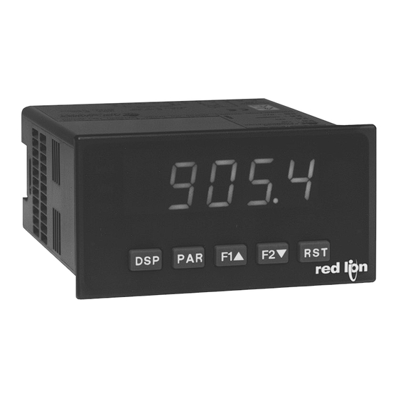
MODEL PAX
U L
C
US LISTED
R
IND. CONT. EQ.
51EB
GENERAL DESCRIPTION
®
The PAX
Analog Panel Meters offer many features and performance
capabilities to suit a wide range of industrial applications. Available in five
different models to handle various analog inputs, including DC Voltage/Current,
AC Voltage/Current, Process, Temperature, and Strain Gage Inputs. Refer to
pages 4 through 6 for the details on the specific models. The option cards allow
the opportunity to configure the meter for present applications, while providing
easy upgrades for future needs.
The meters employ a bright 0.56" LED display. The unit is available with a
red sunlight readable or a standard green LED. The intensity of display can be
adjusted from dark room applications up to sunlight readable, making it ideal
for viewing in bright light applications.
The meters provide a MAX and MIN reading memory with programmable
capture time. The capture time is used to prevent detection of false max or min
readings which may occur during start-up or unusual process events.
The signal totalizer (integrator) can be used to compute a time-input product.
This can be used to provide a readout of totalized flow, calculate service
intervals of motors or pumps, etc. The totalizer can also accumulate batch
weighing operations.
Optional digital output cards provide the meter with up to four setpoint
outputs. The cards are available as dual relay, quad relay, quad sinking
transistor, quad sourcing transistor/SSR drive, or dual triac/dual SSR drive
outputs. The setpoint alarms can be configured to suit a variety of control and
alarm requirements.
Communication and Bus Capabilities are also available as option cards.
These include RS232, RS485, Modbus, DeviceNet, and Profibus-DP. Readout
values and setpoint alarm values can be controlled through the bus. Additionally,
the meters have a feature that allows a remote computer to directly control the
outputs of the meter. With an RS232 or RS485 card installed, it is possible to
DIMENSIONS In inches (mm)
MA
X
8. 8 . 8 . 8 . 8
V
M
N I
T T
O
SP
SP
S
3
S
1
2
P
P4
DSP
PAR
F1
F2
RST
3.80
(96.5)
– 1/8 DIN ANALOG INPUT PANEL METERS
Note: Recommended minimum clearance (behind the panel) for mounting clip installation is
2.1" (53.4) H x 5.0" (127) W.
1.95
(49.5)
.10
(2.5)
PROCESS, VOLTAGE, CURRENT, TEMPERATURE, AND STRAIN
GAGE INPUTS
5-DIGIT 0.56" RED SUNLIGHT READABLE DISPLAY
VARIABLE INTENSITY DISPLAY
16 POINT SCALING FOR NON-LINEAR PROCESSES
PROGRAMMABLE FUNCTION KEYS/USER INPUTS
9 DIGIT TOTALIZER (INTEGRATOR) WITH BATCHING
OPTIONAL CUSTOM UNITS OVERLAY W/BACKLIGHT
FOUR SETPOINT ALARM OUTPUTS (W/OPTION CARD)
COMMUNICATION AND BUS CAPABILITIES (W/OPTION CARD)
RETRANSMITTED ANALOG OUTPUT (W/OPTION CARD)
®
CRIMSON
PROGRAMMING SOFTWARE
NEMA 4X/IP65 SEALED FRONT BEZEL
configure the meter using a Windows
can be saved to a file for later recall.
A linear DC output signal is available as an optional card. The card provides
either 20 mA or 10 V signals. The output can be scaled independent of the input
range and can track either the input, totalizer, max or min readings.
Once the meters have been initially configured, the parameter list may be
locked out from further modification in its entirety or only the setpoint values
can be made accessible.
The meters have been specifically designed for harsh industrial environments.
With NEMA 4X/IP65 sealed bezel and extensive testing of noise effects to CE
requirements, the meter provides a tough yet reliable application solution.
SAFETY SUMMARY
All safety related regulations, local codes and instructions that appear in this
literature or on equipment must be observed to ensure personal safety and to
prevent damage to either the instrument or equipment connected to it. If
equipment is used in a manner not specified by the manufacturer, the protection
provided by the equipment may be impaired.
Do not use this unit to directly command motors, valves, or other actuators
not equipped with safeguards. To do so can be potentially harmful to persons or
equipment in the event of a fault to the unit.
CAUTION: Risk of Danger
Read complete instructions prior to
installation and operation of the unit.
1.75
(44.5)
4.10
(104.1)
1
Bulletin No. PAX-R
Drawing No. LP0545
Released 04/16
®
based program. The configuration data
CAUTION: Risk of electric shock.
12
16
20
13
17
21
14
18
22
15
19
23
24
25
1 2 3 4 5 6
7
8 9 10 11
3.60 (91.4)
1.75
(44.5)
Advertisement
Table of Contents

Related Manuals for red lion PAX


Summary of Contents for red lion PAX
-
Page 1: General Description
Bulletin No. PAX-R Drawing No. LP0545 Released 04/16 Tel +1 (717) 767-6511 Fax +1 (717) 764-0839 www.redlion.net ® MODEL PAX – 1/8 DIN ANALOG INPUT PANEL METERS PROCESS, VOLTAGE, CURRENT, TEMPERATURE, AND STRAIN GAGE INPUTS 5-DIGIT 0.56" RED SUNLIGHT READABLE DISPLAY ... -
Page 2: Programming Overview
SFCRD200 * This card is not suitable for use in older PAX models. For proper installation, a case knock-out feature must be present on the top surface of the PAX case. This feature began to be introduced to the standard PAX units in July of 2014 (2614). -
Page 3: Environmental Conditions
eneral eTer peCifiCaTiOns 1. DISPLAY: 5 digit, 0.56" (14.2 mm) red sunlight readable or standard green 14. MEMORY: Nonvolatile E PROM retains all programmable parameters and LEDs, (-19999 to 99999) display values. 2. POWER: 15. ENVIRONMENTAL CONDITIONS: AC Versions: Operating Temperature Range: 0 to 50°C (0 to 45°C with all three option AC Power: 85 to 250 VAC, 50/60 Hz, 15 VA cards installed) Isolation: 2300 Vrms for 1 min. - Page 4 paXd - U dC i Odel niversal npUT FOUR VOLTAGE RANGES (300 VDC Max) FIVE CURRENT RANGES (2A DC Max) THREE RESISTANCE RANGES (10K Ohm Max) SELECTABLE 24 V, 2 V, 1.75 mA EXCITATION PAXD SPECIFICATIONS INPUT RANGES: INPUT ACCURACY*...
- Page 5 paXH - aC T rms v Odel OlT and UrrenT FOUR VOLTAGE RANGES (300 VAC Max) FIVE CURRENT RANGES (5 A Max) ACCEPTS AC OR DC COUPLED INPUTS THREE WAY ISOLATION: POWER, INPUT AND OUTPUTS PAXH SPECIFICATIONS INPUT RANGES: Isolation To Option Card Commons and User Input Commons: 125 Vrms Isolation To AC Power Terminals: 250 Vrms...
-
Page 6: Rtd I Nput
The meter’s program can then be saved installed into the meter’s bezel display assembly. in a PC file for future use. A PAX serial option card or PAX USB programming card is required to program the meter using the software. Crimson can be EXTERNAL CURRENT SHUNTS (APSCM) downloaded at www.redlion.net. - Page 7 Adding Option Cards DUAL RELAY CARD: PAXCDS10 The PAX and MPAX series meters can be fitted with up to three option cards. Type: Two FORM-C relays The details for each option card can be reviewed in the specification section Isolation To Sensor &...
-
Page 8: Setting The Jumpers
The panel The PAX meets NEMA 4X/IP65 requirements when properly installed. The latch should be engaged in the farthest forward slot possible. To achieve a unit is intended to be mounted into an enclosed panel. -
Page 9: Jumper Selections
PAXD Jumper Selection Input Range Jumper One jumper is used for voltage/ohms or current input ranges. Select the proper input range high enough to avoid input signal overload. Only one jumper is allowed in this area. Do not have a jumper in both the voltage and current ranges at the same time. - Page 10 PAXP Jumper Selection Main Circuit JUMPER SELECTIONS Board indicates factory setting. USER INPUT LOGIC JUMPER SINK SOURCE REAR TERMINALS USER INPUT JUMPER LOCATION PAXS Jumper Selection Bridge Excitation One jumper is used to select bridge excitation to allow use of the higher sensitivity 24 mV input Main range.
-
Page 11: Top View
These cards plug into the main circuit board of the meter. The option main circuit board connector locations. When installing the card, hold the cards have many unique functions when used with the PAX. meter by the rear terminals and not by the front display board. -
Page 12: W Iring The M Eter
Visit RLC’s web site at http://www.redlion.net/emi for more information on a. Connect the shield to earth ground (protective earth) at one end where the EMI guidelines, Safety and CE issues as they relate to Red Lion Controls unit is mounted. -
Page 13: Input Signal Wiring
4.2 INPUT SIGNAL WIRING PAXD INPUT SIGNAL WIRING Before connecting signal wires, the Input Range Jumper and Excitation Jumper should be verified for proper position. Voltage Signal Current Signal Current Signal (2 wire Current Signal (3 wire (self powered) (self powered) requiring excitation) requiring excitation) Terminal 4: -ADC... - Page 14 PAXH INPUT SIGNAL WIRING Before connecting signal wires, the Signal, Input Range and Couple Jumpers should be verified for proper position. Voltage Signal Current Signal (Amps) Current Signal (Milliamps) CAUTION: Connect only one input signal range to the meter. Hazardous signal levels may be present on unused inputs.
-
Page 15: User Input Wiring
4.3 USER INPUT WIRING Before connecting the wires, the User Input Logic Jumper should be verified for proper position. If not using User Inputs, then skip this section. Only the appropriate User Input terminal has to be wired. Sinking Logic Sourcing Logic Terminal 8-10: Terminal 8-10: + VDC thru external switching device... -
Page 16: Programming Mode
6.0 p rOgramming THe eTer OVERVIEW DISPLAY MODE PROGRAMMING MENU MAIN MENU User Input/ Display/ Signal Function Program Secondary Totalizer Setpoint* Serial* Analog* Factory Input Lock-out Function (Integrator) (Alarm) Communication Output Service Parameters Parameters Operations Parameters Parameters Parameters Parameters Parameters Parameters F1/F2 Keys... - Page 17 6.1 mOdUle 1 - s ignal npUT arameTers PAX PARAMETER MENU 1-INP PAXH ONLY rAN6E COUPL dECPt round FILtr bANd StYLE Input Input Display Display Filter Filter Scaling Scaling Input x Display x Range Couple Decimal Point Rounding Setting...
- Page 18 DISPLAY ROUNDING SCALING POINTS Bottom row selections are not Linear - Scaling Points (2) available for the PAXT. For linear processes, only 2 scaling points are necessary. It is recommended that the 2 scaling points be at opposite ends of the input signal being applied.
-
Page 19: Parameter Menu
DISPLAY VALUE FOR SCALING POINT 2 4. The maximum scaled Display Value spread between range maximum and minimum is limited to 65,535. For example using +20 mA range the maximum +20 mA can be scaled to is 32,767 with 0 mA being 0 and Display ... - Page 20 HOLD DISPLAY RESET MAXIMUM When activated (momentary action), flashes and The shown display is held but all other meter functions continue as long as activated (maintained action). the Maximum resets to the present Input Display value. The ...
- Page 21 SETPOINT SELECTIONS PRINT REQUEST The following selections are accessible only with the Setpoint option card installed. Refer to Module 6 for an explanation of their operation. ì Select main or alternate setpoints ...
- Page 22 6.4 mOdUle 4 - s eCOndary UnCTiOn arameTers PARAMETER MENU 4-SEC PAXS PAXS PAXT ONLY ONLY PAXT ONLY HI-t LO-t dSP-t At-t At-b b-LIt OFFSt Max. Capture Min. Capture Display Update Auto-Zero Auto-Zero Units Label Display Offset Ice Point Delay Time Delay Time Time...
- Page 23 6.5 mOdUle 5 - T OTalizer nTegraTOr arameTers 5-tOt PARAMETER MENU dECPt tbASE SCFAC Locut P-UP Totalizer Totalizer Totalizer Totalizer Low Totalizer Power Decimal Point Time Base Scale Factor Cut Value Up Reset TOTALIZER HIGH ORDER DISPLAY The totalizer accumulates (integrates) the Input Display value using one of two modes.
- Page 24 6.6 mOdUle 6 - s ) Ñ eTpOinT larm arameTers PARAMETER MENU 6-SPt SPSEL ACt-n SP-n Src-n HYS-n tON-n tOF-n out-n Setpoint Setpoint Setpoint Setpoint Setpoint On Time Off Time Output Select Value Source Hysteresis Delay Delay Logic Action PAXT ONLY rSt-n...
- Page 25 SETPOINT ACTION ON TIME DELAY sec. Enter the action for the selected setpoint (alarm output). See Setpoint Alarm Enter the time value in seconds that the alarm is delayed from turning on after Figures for a visual detail of each action.
-
Page 26: Baud Rate
SETPOINT ANNUNCIATORS MANUAL RESET SP - Hys mode disables display setpoint annunciators. The mode displays the corresponding setpoint annunciators of “on” alarm outputs. The mode displays the corresponding setpoint annunciators of “off” alarms ì... -
Page 27: Print Options
Register Identification Chart ABBREVIATED PRINTING Register Value Description Applicable Commands/Comments (Reset command [Ver2.5+] Input T, P, R zeros the input [“REL” or Tare]) (Reset command resets total to Select abbreviated transmissions (numeric only) or full field transmission. Total T, P, R zero) - Page 28 250<CR><LF><SP><CR><LF> The abbreviated response suppresses the node address and register ID, leaving only the numeric part of the response. SERIAL COMMANDS FOR PAX SOFTWARE (CSR) Control Status Register Examples: The Control Status Register is used to both directly control the meter’s 1.
-
Page 29: Communication Format
Given this limitation, the parity bit is often ignored by the command and when complete, performs the command function. This time receiving device. The PAX meter ignores the parity bit of incoming data and interval t varies from 2 msec to 50 msec. If no response from the meter is sets the parity bit to odd, even or none (mark parity) for outgoing data. - Page 30 6.8 mOdUle 8 - a ) Ñ nalOg UTpUT arameTers PARAMETER MENU 8-Out PAXT ONLY tYPE ASIN AN-LO AN-HI burn Analog Analog Burn-out Analog Analog Low Analog High Type Update Time Action Assignment Scale Value Scale Value Ñ - An analog output card must be installed in order to access this module.
-
Page 31: Restore Factory Defaults
6.9 mOdUle 9 - f aCTOry erviCe peraTiOns 9-FCS PARAMETER MENU d-LEV COdE Display Factory Intensity Level Service Code DISPLAY INTENSITY LEVEL PAXP - Input Calibration Enter the desired Display Intensity Level (0-15) by WARNING: Calibration of this meter requires a signal source with an using the arrow keys. - Page 32 10. Restore original configuration and jumper settings. 3. Using the chart below, step through the five selections to be calibrated. At each prompt, use the PAX arrow keys to adjust the external meter display to match the selection being calibrated. When the external reading matches, or if this range is not being calibrated, press PAR.
-
Page 33: Troubleshooting
PROGRAM: Module 4 as Hi-t: 0.0 LO-t: 3271.1 (to disable zero chop feature) For further assistance, contact technical support at the appropriate company numbers listed. PARAMETER VALUE CHART Programmer ________________ Date ________ PAX MODEL NUMBER ________ Meter# _____________ Security Code __________ Signal Input Parameters ... - Page 34 User Input and Function Key Parameters Totalizer (Integrator) Parameters FACTORY FACTORY DISPLAY PARAMETER USER SETTING DISPLAY PARAMETER USER SETTING SETTING SETTING * TOTALIZER DECIMAL POINT USER INPUT 1 TOTALIZER TIME BASE USER INPUT 2 ...
- Page 35 QUiCK OvervieW...
-
Page 36: Limited Warranty
LIMITED WARRANTY (a) Red Lion Controls Inc., Sixnet Inc., N-Tron Corporation, or Blue Tree Wireless Data, Inc. (the “Company”) warrants that all Products shall be free from defects in material and workmanship under normal use for the period of time provided in “Statement of Warranty Periods”...
Need help?
Do you have a question about the PAX and is the answer not in the manual?
Questions and answers