Table of Contents
Advertisement
Quick Links
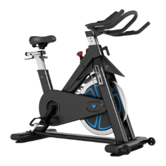
SP-870 M3 Spin Bike
Read all instructions carefully before using this product.
Retain this owner's manual for future reference.
IMPORTANT
All nuts and bolts are to be checked and tightened on a regular basis. This includes pedals and
other moving parts. Failure to do so may cause damage to your threads and void your warranty.
NOTE:
Product may vary slightly from the item pictured due to model upgrades. This manual may be subject to updates or changes.
Up to date manuals are available through our website at www.lifespanfitness.com.au
USER MANUAL
Advertisement
Table of Contents

Related Manuals for LifeSpan SP-870 M3


Summary of Contents for LifeSpan SP-870 M3
- Page 1 SP-870 M3 Spin Bike USER MANUAL Read all instructions carefully before using this product. Retain this owner’s manual for future reference. IMPORTANT All nuts and bolts are to be checked and tightened on a regular basis. This includes pedals and other moving parts.
-
Page 2: Table Of Contents
TABLE OF CONTENTS Important Safety Instructions ....... 03 II. Care Instructions ..........04 III. -
Page 3: Important Safety Instructions
I. IMPORTANT SAFETY INSTRUCTIONS WARNING: Read all instructions before using this machine. It is important your machine receives regular maintenance to prolong its useful life. Failing to regularly maintain your machine may void your warranty. Please always keep this manual with you. •... -
Page 4: Care Instructions
• Always keep this instruction manual and assembly tools at hand for reference. • The equipment is not suitable for therapeutic use. • The pulse or heart rate sensors are not medical devices. Various factors, including the user’s movement, may affect the accuracy of heart rate readings. The pulse sensors are intended only as exercise aids in determining heart rate trends in general. -
Page 5: Exploded Diagram
III. EXPLODED DIAGRAM EXPLODED DIAGRAM |... -
Page 6: Parts List
IV. PARTS LIST Name Quantity Spec. Tube Plug 100*50*20 φ52*43(M8X25) Adjustment Foot Carriage Bolt M8X62 Rear Stabilizer WELDMENT Flat Washer Domed Nut Hex Head Bolt M8*40 Bearing 608ZZ φ69X26 Wheel Bolt M8*15 Front Stabilizer WELDMENT Adjustment Knob M10*20 φ25*φ11/t2.5 Flat Washer Adjustment Knob M16*25 φ40.6*60... - Page 7 Name Quantity Spec. Hex Flange Surface Nut 2 M12X1.25 Pedal 1SET JD-304V M20*1.5/L Pedal 1SET JD-304V M20*1.5/R Left Crank M20*1.5-LH Right Crank M20*1.5 Protection Cover 735*325*67 Screw ST4.2X9.5 F Screw ST4.2X19 Belt 1360mm Bolt M8*18 φ25*182 Mandrel φ200*24 Pulley Elastic Washer Lock Nut φ30*φ25.05*9 Metal Tube...
- Page 8 Name Quantity Spec. Bolt M6*12 match Φ25 tube Pulse Sensor Pulse Sensor Line L=700 Bolt M5*12 Computer ST-7607 L=50 Sensing Line L=850 Sensor LTF8163 Left and Right Hand 80*16*10 Connect the Rod Assembly WELDMENT Handle 70*58*20 Φ5*56 Long Shaft Φ8*50.5 Step Shaft Bolt M5*12...
-
Page 9: Assembly Instructions
V. ASSEMBLY INSTRUCTIONS NOTE: Before assembly ensure there is enough space around the item. Check and count all parts are present. NOTE: Some nuts and bolts may be already attached to the machine. STEP 1 STEP 2 1. Lock the Front Stabilizer (pt.11) to the Main 1. - Page 10 5 52 Convex point ATTENTION: Connected with the computer line, to Gap (A1) corresponding to the convex point (A2) to insert link. STEP 3 1. Insert the Handlebar Post (pt.19) into the handlebar post tube of the main frame. You will have to slacken the Knob (pt.14) and pull the knob back.
- Page 11 STEP 4 1. The Pedals (pt.42L & pt.42R) are marked "L" and "R" - Left and Right. Connect them to their appropriate crank arms. The right crank arm is on the right-hand side of the cycle as you sit on it. NOTE: That the Right pedal should be threaded on clockwise and the Left pedal anticlockwise.
- Page 12 SEAT ADJUSTMENT UP/DOWN To adjust the seat height, hold onto the seat and pull the seat post up to your desired height. To lower it you will need to pull the release lever underneath the seat up and while holding the lever, push the seat down, then release the lever to lock into position.
-
Page 13: Computer Operation
VI. COMPUTER OPERATION DISPLAY OPERATIONS Item Description Displays the current workout duration. TIME Measuring range: 0:00 to 99:59 Displays the user’s workout speed. SPEED Measuring range: 0.0 to 99.9 Displays the user’s workout distance. DISTANCE Measuring range: 0.0 to 99.9 Displays the user’s approximate calories burnt during workout. - Page 14 OPERATION PROCEDURE Powering On the Machine The monitor requires 4x AA batteries to function. Once the batteries are installed, hold RESET for 2 seconds to power on the monitor. The monitor will buzz for 1 second to confirm. Once powered on, the LCD will display all functions for 2 seconds and then display the wheel diameter and units for 1 second.
- Page 15 Workout Mode Selection Use the control wheel to select a workout mode: Choose quick start or set a specific goal for the workout, such as: 1. Target Time 2. Target Distance 3. Target Calories 4. Target Heart Rate 5. Target Watt 6.
- Page 16 Target Distance 1. Use the control wheel to set Target DISTANCE (Preset value = 5.0), press START/STOP to begin workout in Target Distance mode. 2. DISTANCE begins to count down from Target value, TIME, CALORIES, RPM, SPEED, WATT, HEART RATE will be displayed accordingly.
- Page 17 Target Watt 1. Use the control wheel to set the Target WATT (preset value = 100), press START/STOP to begin workout in Target Watt mode. 2. TIME begins to count up, DISTANCE, CALORIES, RPM, SPEED, WATT, HEART RATE will be displayed accordingly.
- Page 18 Watt Program 1. Use control wheel to select: Beginner, Advanced or Sporty and press MODE to confirm. 2. Use control wheel to set Time (preset value = 30:00), press START/STOP to begin workout in Watt Program mode. 3. TIME begins to count down from Target value, DISTANCE, CALORIES, RPM, SPEED, WATT, HEART RATE will be displayed accordingly.
-
Page 19: Exercise Guide
VII. EXERCISE GUIDE PLEASE NOTE: Before beginning any exercise program, consult your physician. This is important especially if you are over the age of 45 or individuals with pre-existing health problems. The pulse sensors are not medical devices. Various factors, including the user’s movement, may affect the accuracy of heart rate readings. - Page 20 COOL DOWN Finish each workout with a light jog or walk for at least 1 minute. Then complete 5 to 10 minutes of stretching to cool down. This will increase the flexibility of your muscles and will help prevent post- exercise problems.
-
Page 21: Warranty
Any claim against this warranty must be made through your original place of purchase. Proof of purchase is required before a warranty claim may be processed. If you have purchased this product from the Official Lifespan Fitness website, please visit https://lifespanfitness.com.au/warranty-form For support outside of warranty, if you wish to purchase replacement parts or request a repair or service, please visit https://lifespanfitness.com.au/warranty-form and fill in our Repair/Service... -
Page 22: Hand Pulse Technology
IX. HAND PULSE TECHNOLOGY This product comes equipped with hand pulse sensors which are used to pick up tiny EKG/ECG signals that run through the body when your heart beats. These electrical EKG/ECG signals are very small and must be amplified 1000 times to make the signal viable for the computer to display your pulse. To ensure proper operation: •... - Page 24 WWW.LIFESPA NF ITN ES S.COM.AU...
Need help?
Do you have a question about the SP-870 M3 and is the answer not in the manual?
Questions and answers