Sign In
Upload
Manuals
Brands
IEI Technology Manuals
Computer Hardware
KINO-ABT-i2 Series
IEI Technology KINO-ABT-i2 Series Manuals
Manuals and User Guides for IEI Technology KINO-ABT-i2 Series. We have
1
IEI Technology KINO-ABT-i2 Series manual available for free PDF download: User Manual
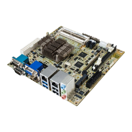
IEI Technology KINO-ABT-i2 Series User Manual (158 pages)
Mini-ITX SBC with 22nm Intel Atom or Celeron SoC, Dual GbE, DDR3, HDMI, VGA, DisplayPort, USB 3.0, COM, SATA 3Gb/s, IPMI 2.0 and RoHS
Brand:
IEI Technology
| Category:
Computer Hardware
| Size: 9 MB
Table of Contents
Table of Contents
5
Introduction
15
Introduction
16
Figure 1-1: KINO-ABT-I2
16
Model Variations
17
Table 1-1: Model Variations
17
Benefits
18
Features
18
Connectors
19
Figure 1-2: Connectors
19
Dimensions
20
Figure 1-3: KINO-ABT-I2 Main Dimensions (MM)
20
Data Flow
21
Figure 1-4: Data Flow Diagram
21
Technical Specifications
22
Table 1-2: KINO-ABT-I2 Specifications
24
Packing List
25
Anti-Static Precautions
26
Unpacking Precautions
26
Packing List
27
Optional Items
28
Table 2-1: Packing List
28
Table 2-2: Optional Items
29
Connectors
30
Peripheral Interface Connectors
31
KINO-ABT-I2 Layout
31
Figure 3-1: Connectors and Jumpers
31
Peripheral Interface Connectors
32
External Interface Panel Connectors
33
Table 3-1: Peripheral Interface Connectors
33
Table 3-2: Rear Panel Connectors
33
Internal Peripheral Connectors
34
ATX Power Connector
34
Figure 3-2: ATX Power Connector Location
34
Audio Connector
35
Figure 3-3: Audio Connector Location
35
Table 3-3: ATX Power Connector Pinouts
35
Table 3-4: Audio Connector Pinouts
35
Battery Connector
36
Figure 3-4: Battery Connector Location
36
Table 3-5: Battery Connector Pinouts
36
Chassis Intrusion Connector
37
Digital I/O Connector
37
Figure 3-5: Chassis Intrusion Connector Location
37
Table 3-6: Chassis Intrusion Connector Pinouts
37
Displayport Connector
38
Figure 3-6: Digital I/O Connector Location
38
Table 3-7: Digital I/O Connector Pinouts
38
EC Debug Connector
39
Figure 3-7: Displayport Connector Location
39
Table 3-8: Displayport Connector Pinouts
39
Fan Connector (CPU)
40
Figure 3-8: EC Debug Connector Location
40
Table 3-9: EC Debug Connector Pinouts
40
Fan Connector (System)
41
Figure 3-9: CPU Fan Connector Location
41
Table 3-10: CPU Fan Connector Pinouts
41
Front Panel Connector
42
Figure 3-10: System Fan Connector Location
42
Table 3-11: System Fan Connector Pinouts
42
Iris Module Slot
43
Figure 3-11: Front Panel Connector Location
43
Table 3-12: Front Panel Connector Pinouts
43
Keyboard and Mouse Connector
44
Figure 3-12: Iris Module Slot Location
44
LAN LED Connectors
45
Figure 3-13: Keyboard and Mouse Connector Location
45
Table 3-13: Keyboard and Mouse Connector Pinouts
45
Memory Card Slot(S)
46
Figure 3-14: LAN LED Connector Locations
46
Table 3-14: LAN1 LED Connector Pinouts
46
Table 3-15: LAN2 LED Connector Pinouts
46
Pcie X4 Slot
47
Figure 3-15: Memory Card Slot Locations
47
Pcie Mini Card Slot
48
Figure 3-16: Pcie X4 Slot Location
48
Figure 3-17: Pcie Mini Card Slot Location
48
Table 3-16: Pcie Mini Card Slot Pinouts
49
Power Button
50
Reset Button Connector
50
Figure 3-18: Power Button Location
50
SATA 3Gb/S Drive Connectors
51
Figure 3-19: Reset Button Connector Location
51
Table 3-17: Reset Button Connector Pinouts
51
SATA Power Connectors
52
Figure 3-20: SATA 3Gb/S Drive Connector Locations
52
Table 3-18: SATA 3Gb/S Drive Connector Pinouts
52
Serial Port Connectors, RS-232
53
Figure 3-21: SATA Power Connector Locations
53
Table 3-19: SATA Power Connector Pinouts
53
Serial Port Connector, RS-422/485
54
Figure 3-22: RS-232 Serial Port Connector Locations
54
Table 3-20: RS-232 Serial Port Connector Pinouts
54
Figure 3-23: RS-422/485 Connector Location
55
Table 3-21: RS-422/485 Connector Pinouts
55
Table 3-22: RS-422/485 Pinouts of D-Sub 9 Connector
55
Smbus Connector
56
SPDIF Connector
56
Figure 3-24: Smbus Connector Location
56
Table 3-23: Smbus Connector Pinouts
56
SPI Flash Connector
57
Figure 3-25: SPDIF Connector Location
57
Table 3-24: SPDIF Connector Pinouts
57
SPI Flash Connector, EC
58
Figure 3-26: SPI Flash Connector Location
58
Table 3-25: SPI Flash Connector Pinouts
58
TPM Connector
59
Figure 3-27: SPI EC Flash Connector Location
59
Table 3-26: SPI EC Flash Connector Pinouts
59
USB 2.0 Connectors
60
Figure 3-28: TPM Connector Location
60
Table 3-27: TPM Connector Pinouts
60
Figure 3-29: USB 2.0 Connector Locations
61
Table 3-28: USB1 Pinouts
61
Table 3-29: USB2 Pinouts
61
External Peripheral Interface Connector Panel
62
Audio Connector
62
Figure 3-30: External Peripheral Interface Connector
62
Ethernet and USB 2.0 Combo Connector
63
Figure 3-31: Audio Connector
63
Table 3-30: LAN2 Ethernet Connector Pinouts
63
Ethernet and USB 3.0 Combo Connector
64
Figure 3-32: Ethernet Connector
64
Table 3-31: Connector Leds
64
Table 3-32: USB 2.0 Port Pinouts
64
Figure 3-33: Ethernet Connector
65
Table 3-33: LAN1 Ethernet Connector Pinouts
65
Table 3-34: Connector Leds
65
Table 3-35: USB 3.0 Port Pinouts
65
HDMI Connector
66
Figure 3-34: HDMI Connector
66
Table 3-36: HDMI Connector Pinouts
66
Serial Port Connectors (COM1 and COM2)
67
VGA Connector
67
Figure 3-35: Serial Port Pinouts
67
Table 3-37: Serial Port Pinouts
67
Figure 3-36: VGA Connector
68
Table 3-38: VGA Connector Pinouts
68
Installation
69
Anti-Static Precautions
70
Installation Considerations
70
SO-DIMM Installation
72
Iris-2400 Module Installation
72
Figure 4-1: SO-DIMM Installation
72
Figure 4-2: Iris Module Installation
73
Pcie Mini Card Installation
74
Figure 4-3: Pcie Mini Card Retention Screw Removal
74
System Configuration
75
AT/ATX Power Mode Setting
75
Figure 4-4: Pcie Mini Card Installation (Full-Size)
75
Figure 4-5: AT/ATX Power Mode Switch Location
75
Clear CMOS Button
76
Flash Descriptor Security Override
76
Figure 4-6: Clear CMOS Button Location
76
Figure 4-7: Flash Descriptor Security Override Jumper Location
76
Table 4-1: Flash Descriptor Security Override Jumper Settings
76
Msata/Sata Selection
77
USB Power Select
77
Figure 4-8: Msata/Sata Switch Location
77
Table 4-2: Msata/Sata Switch Settings
77
Table 4-3: BIOS Options and Configured USB Ports
77
Internal Peripheral Device Connections
78
SATA Drive Connection
78
Figure 4-9: SATA Drive Cable Connection
78
USB Cable Connection
79
Figure 4-10: Dual USB Cable Connection
79
Ipmi Setup Procedure
80
Managed System Hardware Setup
80
Using the IEI Iman Web GUI
80
Figure 4-11: IEI Iman Web Address
81
Figure 4-12: IEI Iman Web GUI
81
Bios
83
Introduction
84
Starting Setup
84
Using Setup
84
Getting Help
85
Unable to Reboot after Configuration Changes
85
BIOS Menu Bar
85
Table 5-1: BIOS Navigation Keys
85
Main
86
BIOS Menu 1: Main
86
Advanced
88
ACPI Settings
88
BIOS Menu 2: Advanced
88
BIOS Menu 3: ACPI Configuration
89
Super IO Configuration
90
Serial Port N Configuration
90
BIOS Menu 4: Super IO Configuration
90
BIOS Menu 5: Serial Port N Configuration Menu
90
Iwdd Hardware Monitor
98
BIOS Menu 6: Iwdd Hardware Monitor
99
Smart Fan Function
100
BIOS Menu 7: Smart Fan Function
100
RTC Wake Settings
102
BIOS Menu 8: RTC Wake Settings
102
Serial Port Console Redirection
103
BIOS Menu 9: Serial Port Console Redirection
104
CPU Configuration
106
BIOS Menu 10: CPU Configuration
106
IDE Configuration
108
BIOS Menu 11: IDE Configuration
108
Trusted Computing
110
BIOS Menu 12: Trusted Computing
110
USB Configuration
111
BIOS Menu 13: USB Configuration
111
Chipset
112
BIOS Menu 14: Chipset
112
North Bridge
113
Intel IGD Configuration
113
BIOS Menu 15: North Bridge
113
BIOS Menu 16: Intel IGD Configuration
113
South Bridge
115
BIOS Menu 17: South Bridge
115
Table 5-2: BIOS Options and Configured USB Ports
116
Azalia HD Audio
117
BIOS Menu 18: Azalia HD Audio
117
PCI Express Configuration
118
BIOS Menu 19: PCI Express Configuration
118
Security
119
BIOS Menu 20: Security
119
Boot
120
BIOS Menu 21: Boot
120
Exit
122
BIOS Menu 22:Exit
122
Software Drivers
124
Available Software Drivers
125
Software Installation
125
Figure 6-1: Driver CD Main Menu
126
Figure 6-2: Available Drivers
126
Chipset Driver Installation
127
Figure 6-3: Chipset Driver Welcome Screen
127
Figure 6-4: Chipset Driver License Agreement
128
Figure 6-5: Chipset Driver Read Me File
128
Figure 6-6: Chipset Driver Setup Operations
129
Figure 6-7: Chipset Driver Installation Finish Screen
129
Graphics Driver Installation
130
Figure 6-8: Graphics Driver Welcome Screen
131
Figure 6-9: Graphics Driver License Agreement
131
Figure 6-10: Graphics Driver Read Me File
132
Figure 6-11: Graphics Driver Setup Operations
132
Lan Driver Installation
133
Figure 6-12: Graphics Driver Installation Finish Screen
133
Figure 6-13: PC Properties
134
Figure 6-14: System Control Panel
134
Figure 6-15: Device Manager List
135
Figure 6-16: Update Driver Software Window
136
Figure 6-17: Locate Driver Files
136
A Regulatory Compliance
138
B Product Disposal
140
CBIOS Options
142
D Terminology
145
E Digital I/O Interface
150
F Watchdog Timer
153
G Hazardous Materials Disclosure
156
Advertisement
Advertisement
Related Products
IEI Technology KINO-DH310
IEI Technology KINO-DQM170
IEI Technology KINO-DH420
IEI Technology KINO-EHL Series
IEI Technology KINO-EHL2
IEI Technology KINO-ATOM
IEI Technology KINO-ADL-H610
IEI Technology KINO-ADL-P
IEI Technology KINO-ADL-P-i3-R10
IEI Technology KINO-AA750-i2
IEI Technology Categories
Motherboard
Touch Panel
Computer Hardware
Single board computers
Desktop
More IEI Technology Manuals
Login
Sign In
OR
Sign in with Facebook
Sign in with Google
Upload manual
Upload from disk
Upload from URL