
Related Manuals for M&C TEC1 Series


Summary of Contents for M&C TEC1 Series
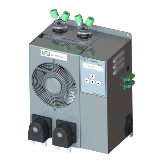
- Page 1 TEC1 Series Thermoelectric Chiller For General Purpose Areas OPERATIONS MANUAL M&C Ventura, CA Office: 805-654-6970 ● M&C Reno, NV Office: Phone: 775-825-5111 TEC1 Manual Rev. 20180928...
- Page 2 M&C ADVANTAGES M&C products and systems are designed to provide long lasting service and reliability. This is the reason why over 5,000 customers worldwide have confidence in our products and return time and again to provide them with their compliance or process monitoring solutions.
-
Page 3: Table Of Contents
TABLE OF CONTENTS M&C ADVANTAGES ..........................2 INTRODUCTION ............................4 SAFETY INSTRUCTIONS ..........................4 Definition of Symbols ..........................4 GENERAL INFORMATION ..........................6 LIMITED WARRANTY ..........................7 PRODUCT IDENTIFICATION ........................7 APPLICATION ............................8 FUNCTION OF THE M&C JET-STREAM HEAT EXCHANGER ................9 DESCRIPTION ............................ -
Page 4: Introduction
INTRODUCTION The product described in this operating manual has been inspected and tested prior to shipment from our factory to insure proper function, finish and conformance with safety requirements. For safe operation and trouble-free service it is important to heed the notes and warnings made in this operating manual. Transport and storage environments must not exceed the conditions detailed on the specifications page. - Page 5 Protective Conductor Terminal PROTECTIVE CONDUCTOR TERMINAL SYMBOL INDICATES THE TERMINAL LOCATION FOR THE PROTECTIVE CONDUCTOR. FAILURE TO CONNECT TO THE PROTECTIVE CONDUCTOR TERMINAL TO SUITABLE GROUND POTENTIAL MAY RESULT IN A SHOCK HAZARD. Hot Surface HOT SURFACE CAUTION SYMBOL INDICATES EXPOSED SURFACE TEMPERATURE CAN CAUSE BURNS OR PERSONAL INJURY.
-
Page 6: General Information
GENERAL INFORMATION Please take care of the following basic safety procedures when mounting, starting up or operating this equipment: • Read this operating manual before starting up and using the equipment. The information and warnings given in this operating manual must be heeded. •... -
Page 7: Limited Warranty
The M&C warranty specifically excludes claims of consequential damages due to system downtime or damage to components beyond those supplied by M&C. PRODUCT IDENTIFICATION The TEC1 series has the following part number code designation: TEC1abcXX_YY TEC1 = series designation... -
Page 8: Application
APPLICATION The Peltier Gas Sample Cooler Series TEC1 is a standalone device used in analyzer sample system designs to reduce the dew point of wet gases to a level that is stable and low. Sample gas cooling prevents subsequent condensation in the analyzer. The stability of the dew point is also extremely important at it helps to prevent water vapor cross sensitivity and volumetric error, especially in infrared analyzers. -
Page 9: Function Of The M&C Jet-Stream Heat Exchanger
FUNCTION OF THE M&C JET-STREAM HEAT EXCHANGER The Jet-Stream heat exchangers made of Duran glass, PVDF, Hastelloy or stainless steel and are located in a heat- insulated cooling block. All the heat exchangers are easily accessible and are arranged in such a way that they can be removed very simply. -
Page 10: Description
DESCRIPTION The Series TEC1 Peltier Gas Sample Cooler is supplied complete with a Jet-Stream heat exchanger made either of Duran glass, stainless steel, PVDF or Hastelloy. The exchanger is housed for ease of replacement in a thermally insulated cooling block on the sides of the cooler. -
Page 11: Receipt Of Goods And Storage
RECEIPT OF GOODS AND STORAGE The TEC1 gas cooler is a complete pre-installed unit. • Please take the TEC1 gas cooler and possible special accessories carefully out of the packaging material immediately after arrival, and compare the goods with the items listed on the delivery note. •... -
Page 12: Supply Connections
SUPPLY CONNECTIONS TUBING CONNECTIONS The gas inlet and outlet is located on the top of the cooler and is indicated by arrows on the Jet- Stream heat exchangers. For possible connectors see technical data. Corresponding tube or hose connectors are optionally available by M&C. -
Page 13: Electrical Connections
SUPPLY CONNECTIONS (CONT.) ELECTRICAL CONNECTIONS When connecting the equipment, please ensure that the supply voltage is identical with the information provided on the model type plate. The main AC power supply connection is to a power entry module on the right side of the enclosure. The TEC1 will be supplied as specified by the customer for either 115 VAC or 230 VAC mains voltage. -
Page 14: Options
OPTIONS Sample Pump The TEC1 series chiller is equipped with a dry contact relay that is capable of controlling a sample pump at a maximum capacity of 10A @ 115/230VAC or less. The sample pump is supplied by others. Water Slip Sensor The TEC1 series chiller is equipped with one condensate slip input as standard, and will have a second installed if there are 2 active channels. -
Page 15: Programming
PROGRAMMING The interface of the TEC1 consists of a two row menu driven display and four buttons. Pressing any button will enter the menu structure. The function of each button is as follows: Left: Either moves to the previous menu branch or moves the cursor left Right: Either moves to the next menu branch or moves the cursor right Up: Either moves to the previous menu entry or increments the value of the entry Down: Either moves to the next menu entry or decrements the value of the entry... - Page 16 Alarms The M&C Series TEC1 comes equipped with a Form C dry contact alarm relay to indicate the status of the chiller. The relay operates in failsafe mode, meaning the coil is energized when there are no alarms present. As this relay is a general status alarm, the following alarms, listed in order of severity, will cause the coil on the relay to de-energize.
-
Page 17: Shut Down
SHUT DOWN The area in which the cooler is situated when not in use must be kept free of frost at all times. If the cooler unit is taken out of service for a short time, no particular measures need to be taken. We recommended purging the cooler with inert gas or ambient air while the unit is out of service for a longer time. - Page 18 o Remove the adhesive tape and any surplus thermally conductive paste; o Reconnect the tubing for gas and drain connections. o Do not mix up the hose connections; gas outlet and gas inlet are marked with arrows. • Mounting the Duran glass heat exchangers please notice: o Check the PTFE/Silicon locking Rings for damage.
-
Page 19: Troubleshooting
TROUBLESHOOTING The following table aims to point out possible operational problems and offer solutions to such problems (not applicable during the startup procedure). Problem/Indication Possible cause Action/Check Check for mains supply voltage at terminals No mains supply against nameplate. Neither the display nor the heat sink fan will be operational. -
Page 20: Spare Parts
SPARE PARTS Wear, tear and replacement part requirements depend on specific operating conditions. The recommended quantities are based on experience and are not binding. Part Number Description Common Components 90K0115 Heat transfer grease for heat exchanger installation 740-70103446 24VDC enclosure cooling fan 740-70289104 115VAC heat sink cooling fan 740-70372498... -
Page 21: Technical Specifications
TECHNICAL SPECIFICATIONS... -
Page 22: Drawing Index
DRAWING INDEX • TEC1 with Controller, Outline & Mounting – 03P0003... - Page 23 • TEC1 available options – 03P0005...
- Page 24 THIS PAGE INTENTIONALLY LEFT BLANK...
- Page 25 ® Peristaltic Pump Series SR SR25.2, SR25.2-G, SR25.2-W SR25.3, SR25.3-G, SR25.3-W SR25.6, SR25.6-G, SR25.6-W Instruction Manual Version 1.01.01...
- Page 26 Dear customer, Thank you for buying our product. In this instruction manual you will find all necessary information about this M&C product. The information in the instruction manual is fast and easy to find, so you can start using your M&C product right after you have read the manual. or your M&C authorized distributor.
- Page 27 Content General information ........................4 Declaration of conformity ......................4 Safety instructions........................5 Warranty ............................5 Warning signs and definitions ....................6 Introduction ..........................8 Technical Data ..........................8 Important safety instructions for using the SR25.X-X .............. 9 Description ..........................10 10 Reception and storage ......................
-
Page 28: General Information
Head Office M&C TechGroup Germany GmbH Rehhecke 79 40885 Ratingen Germany Telephone: 02102 / 935 - 0 Fax: 02102 / 935 - 111 E - mail: info@mc-techgroup.com www.mc-techgroup.com 1 GENERAL INFORMATION The product described in this manual has been built and tested in our production facility. All M&C products are packed to be shipped safely. -
Page 29: Safety Instructions
3 SAFETY INSTRUCTIONS Follow these safety directions and instructions regarding installation, commissioning and operation: Read this manual before commissioning and operating the product. Make sure to follow all safety instructions. Installation and commissioning of electrical devices must be carried out only by qualified skilled personnel in compliance with the current regulations. -
Page 30: Warning Signs And Definitions
5 WARNING SIGNS AND DEFINITIONS and/or significant material damage will be the consequence, if the appropriate precautions should not be taken. Danger damage to property may occur if the relevant precautionary measures are not observed. Warning occur if the appropriate safety precautions are not observed. Caution that damage to property can occur if the Caution... - Page 31 Wear protective gloves! Working with chemicals, sharpe objects or extremly high temperatures requires wearing protective gloves. Wear safety glasses! Protect your eyes while working with chemicals or sharpe objects. Wear safety glasses to avoid getting something in your eyes. Wear protective clothes! Working with chemicals, sharpe objects or extremly high temperatures requires wearing protective clothes.
-
Page 32: Introduction
6 INTRODUCTION The peristaltic pump SR25... has been specially developed for the condensate removal in analysis applications. It ensures a continuous condensate discharge at gas sample coolers, condensate collecting vessels, etc. Synchronous motor and gearing unit with return stop make a condensate backflow impossible. The safe disposal of condensate is guaranteed with the pumping capacities stated in the technical data table. -
Page 33: Important Safety Instructions For Using The Sr25.X-X
8 IMPORTANT SAFETY INSTRUCTIONS FOR USING THE SR25.X-X Inhalation hazard possible, if using toxic or asphyxiant gases! Warning Purge peristaltic pump with inert gas or air before opening! If the pump is used for toxic gas or asphyxiant (oxygen-displacing) gas, it needs to be purged with inert gas or air before opening. -
Page 34: Description
9 DESCRIPTION Check the compatibility of the tube material with unknown gases before using the peristaltic pump. Note The peristaltic pump SR25.X-X is self-suctioning and designed for continuous operation. It consists of 3 compact components: synchronous motor, gearing unit with return stop and pump head. -
Page 35: Figure 2 Drilling Pattern For Sr25.X
Figure 2 Drilling pattern for SR25.X Metric dimensions (mm) are rounded. Inch dimensions are for reference only. In case of doubt or conflict, metric units take priority. Figure 3 Dimensions SR25.X-W www.mc-techgroup.com SR25.X-X | 1.01.01... -
Page 36: Reception And Storage
Metric dimensions (mm) are rounded. Inch dimensions are for reference only. In case of doubt or conflict, metric units take priority. Figure 4 Dimensions SR25.X-G 10 RECEPTION AND STORAGE The peristaltic pump is a complete pre-installed unit. Please remove the peristaltic pump carefully from the packaging. Check the scope of the delivery specified on the delivery note. -
Page 37: Installation Instructions
11 INSTALLATION INSTRUCTIONS When installing the pump make sure that accident prevention regulations and safety instructions including those for subsequent operation are observed. The safety instructions in section must be observed. The following ambient conditions must be observed: Ambient temperature during operation: max. +50 °C [122 °F] Protect the pump against water and dust. -
Page 38: Supply Connections
Pump head [outside the cooler housing) Cooler front panel Recommended monting distance Pump motor (inside the cooler housing) Figure 5 SR25.2: Mounting distance between front panel and pump motor 12 SUPPLY CONNECTIONS 12.1 TUBING CONNECTIONS The tube connections are on the upper side of the pump. The standard threaded tube connectors are DN 4/6. -
Page 39: Electrical Connections
The tightness of the connections can only be guaranteed if the connection tubing has a straight rim (hose cutter). Note Aggressive condensate possible! Media residues in tubing! Chemical burns caused by aggressive media possible! Wear protective gloves and protective glasses! Wear proper protective clothing! 12.2 ELECTRICAL CONNECTIONS Connect the cables for the power supply as follows:... -
Page 40: Start-Up
Incorrect system voltage can damage the unit. Before connecting the power supply, make sure that the system voltage corresponds with the voltage shown on the type plate! The supply voltage is only allowed to deviate max. +6% resp. -10% from the Caution specification on the model type plate. -
Page 41: Maintenance
15 MAINTENANCE Before starting any maintenance work, make sure that any work done on the device is in compliance with all relevant regulations and standards. Inhalation hazard possible, if using toxic or asphyxiant gases! Warning Purge peristaltic pump with inert gas or air before opening! If the pump is used for toxic gas or asphyxiant (oxygen-displacing) gas, it needs to be purged with inert gas or air before opening. -
Page 42: Changing The Pump Tubing
15.1 CHANGING THE PUMP TUBING 1 Conveying belt 2 S-bolt 3 Tubing set 4 contact pulley 5 springs Figure 7 Changing the pump tubing For changing the pump tubing please proceed as follows: Unplug the pump from the mains voltage. The device needs to be voltage free. Press conveying belt at the recessed grips and turn S-bolt clockwise up to limit stop;... -
Page 43: Changing Contact Pulleys And Springs
15.2 CHANGING CONTACT PULLEYS AND SPRINGS While mounting, make sure that the center of rotation and the driver are aligned. Use genuine spare parts only! Note Follow these instructions to change the contact pulley and springs: Disconnect the peristaltic pump from power supply; Unscrew nuts of the pump head (wrench size 5.5) 1 Pump head nuts 2 Pump head... -
Page 44: Reassembly Of The Driver
The springs may come in different colorings. This is not a quality impairment. Make sure to use the right spring strength. This can be identified by the spring wire diameter. The standard version for Novoprene pump tubing (Part No. Note 90P1010) has a diameter of 1.1 mm and the reinforced version for FPM-, Acidflex- or Masterflex-tubing (Part No. -
Page 45: Cleaning The Pump Head
15.3 CLEANING THE PUMP HEAD When changing flexible tube or other parts, inspect all parts for dirt before assembling the pump head and clean them if necessary. We recommend to clean the parts with a dry cloth. Solvent should not be used, because it can damage the plastics and synthetic rubber parts. -
Page 46: Spare Parts List
17 SPARE PARTS LIST Wear, tear and replacement part requirements depend on specific operating conditions. The recommended quantities are based on experience and they are not binding. Peristaltic pump SR25.X-X (C) Consumable parts (R) Recommended spare parts (S) Spare parts Recommended quantity being in operation [years] Part No. -
Page 47: Figure 11 Spare Parts (Drawing No.: 2435-1.07.0)
Figure 11 Spare parts (Drawing No.: 2435-1.07.0) www.mc-techgroup.com SR25.X-X | 1.01.01... - Page 48 THIS PAGE INTENTIONALLY LEFT BLANK...
- Page 49 ® Bellows pump series MP MP-F05, MP-F05/R, MP-F10, MP-F10/R Instruction Manual Version 1.04.01...
- Page 50 Dear customer, Thank you for buying our product. In this manual you will find all necessary information about this M&C product. The information in the manual is fast and easy to find, so you can start using your M&C product right after you have read the manual.
- Page 51 Table of Contents General information ........................4 Declaration of conformity ......................4 Warranty ............................5 Warning signs and definitions ....................5 Correct operation ........................7 Wrong operation ......................... 8 Application ..........................9 7.1 MP-F05/R and MP-F10/R with integrated needle ..............9 Technical data ...........................
-
Page 52: General Information
Headquarters M&C TechGroup Germany GmbH Rehhecke 79 40885 Ratingen Germany Phone: +49 - 2102 - 935 - 0 E - mail: info@mc-techgroup.com Website: www.mc-techgroup.com General information The product described in this instruction manual has been built and tested in our production facility. All M&C products are packed to be shipped safely. -
Page 53: Warranty
Warranty In case of a device failure, please contact immediately M&C or your M&C authorized distributor. We have a warranty period of 12 months from the delivery date. The warranty covers only appropriately used products and does not cover the consumable parts. Please find the complete warranty conditions in our terms and conditions. - Page 54 Corrosive! These substances destroy living tissue and equipment upon contact. Do not breathe vapors; avoid contact with skin and eyes. Wear protective gloves! Working with chemicals, sharpe objects or extremly high tempera- tures requires wearing protective gloves. Wear safety glasses! Protect your eyes while working with chemicals or sharpe objects.
-
Page 55: Correct Operation
Correct operation Follow these basic safety precautions during installation, commissioning and operation of the device: Read this instruction manual before commissioning and operating the product. Please make sure to follow all warnings and safety instructions. Installation and commissioning of electrical devices must be carried out only by qualified skilled personnel in compliance with the current regulations. -
Page 56: Wrong Operation
Wrong operation Please make sure to install and operate the pump for the in- tended use described in this instruction manual only. Warning The pump can only be operated within the parameters stated in 8 Technical data . Warning The pump is not designed for liquids or particles. It is prohibited to operate the pump with condensate. -
Page 57: Application
Application The bellows pump MP-F is suitable for 100 % oil-free operation of corrosive gases. The construction and performance of the pump is especially tailored to the requirements of the analysis technique. The pump is gas tight and its operation is maintenance-free. All sample contacting parts of the bellows pump MP-F are corrosion resistant. - Page 58 Figure 1 Needle valve in a half-section view with one quarter removed Service life and reliability of the pump is increased by using a bypass needle valve. This needle valve protects the pump from unnecessary high loads or overload. Figure 2 Pump with bypass needle valve 4.01 www.mc-techgroup.com...
-
Page 59: Technical Data
Technical data Bellows pump MP-F05 /230 V MP-F05 /115 V MP-F10 /230 V MP-F10/115 V Part no. 05 P 1000 05 P 1000a 05 P 1005 02 P 1005a Part no. with needle valve 05 P 1010 05 P 1010a 05 P 1015 05 P 1015a MP-F../R... -
Page 60: Pump Capacities
Pump capacities Figure 3 Pump capacity MP-F05 and MP-F10 Dimensions Figure 4 Dimensions MP-F../R 4.01 www.mc-techgroup.com... -
Page 61: Receiving And Storing The Bellows Pump
Receiving and storing the bellows pump Please remove the bellows pump carefully from the packaging. Check the scope of the delivery specified on the delivery note. Please make sure that you have received all items stated on the delivery note. Please check the unit for any transport damages after receipt and report any complaints to the transport company immediately. -
Page 62: Installation Instructions
Installation instructions All relevant regulations regarding accident prevention and safety need to be met during installation and operation of the pump. High voltage! Working without disconnecting the power supply may cause an electrical Warning shock. Disconnect power supply before any assembly, maintenance or repair work. - Page 63 Aggressive condensate possible. Chemical burns possible due to aggressive media! For general electrical and mechanical work on the pump, wear personal protective equipment (PPE) in accordance with the risk assessment. Condensate accumulated inside the pump head destroys the pump. If it is likely that humidity or condensation occurs, the pump head needs Warning to be rotated 180°...
-
Page 64: Mounting The Pump
10.1 Mounting the pump The mounting site needs to comply with the following requirements: Ambient temperature range during operation: +10 °C to +50 °C / 0 °C to +50 °C for dry sample gas (+50 °F to + 122 °F / +32 °F to + 122 °F for dry sample gas). The pump is rated IP55 (protection class) and it needs to be protected against water and dust ingress. - Page 65 Now you can change the position of the pump head in 90° steps. After rotating the pump head to the selected position, please insert the four flange screws with the lock washers back again and tighten them. Put the lid back on, and secure the lid by tightening the three lid screws. Figure 6 Rotating the pump head www.mc-techgroup.com...
-
Page 66: Electrical Connections
10.3 Electrical connections Be sure to observe all relevant safety regulations during the electrical installation of the pump. The main power supply must be turned off before connecting the pump. Do not operate bellows pumps MP F.. in explosive environments! Danger Incorrect voltage can destroy the device. -
Page 67: Pneumatic Connection
Figure 7 Electrical connection MP-F.. 10.4 Pneumatic connection It is possible to screw the tube connection fittings into the pump head either from the top or side. To screw-in the tube connection fittings from the side, please remove protective plugs from the gas connection threads on the side and screw them into the threads on the top. -
Page 68: Start Up
To connect the suction and pressure line, please loosen the union nut of the compression ring fitting counter clockwise. Be sure to remove the union nut carefully from the fitting. There is a loose clamp ring inside the union nut. Slide the nut over the connecting tube. -
Page 69: Operating The Pump
If there is a chance that components installed downstream of the pump may block or reduce the sample gas flow, it is necessary to install e.g. a pressure relief valve. This prevents the pressure to exceed the maximum permitted operating value. The bellows and valve plates are the only consumable parts of the pump. -
Page 70: Disassembly
Disassembly Before switching off the pump (decommissioning), the pump needs to be purged with inert gas or air, and it needs to be dried. Note Aggressive condensate possible. Chemical burns possible due to aggressive media! For general electrical and mechanical work on the pump, wear personal protective equipment (PPE) in accordance with the risk assessment. -
Page 71: Maintenance
Maintenance It is necessary to schedule maintenance work at least twice a year. The intervals between servicing are dependent on the process and system conditions in your facility. The facility QA/QC plan should address the frequency for maintenance and should be updated based on your operations. - Page 72 Inspect the following Action pump components Pump Check pump for external damages and any leakage in regular inter- vals, at least two times per year. Capacitor Check the conditions of the adhesive covers of the vents in regular intervals. Replace capacitor with damaged adhesive cover. Bellows and valve plates Replace at least when performance of the pump decreases.
-
Page 73: Replacing The Valve Plates
15.1 Replacing the valve plates If you replace the valve plates, we also recommend to replace the O- rings C at the same time. Note For replacing the valve plates, the sample gas fitting To replace the valve plates, proceed as follows: 1. -
Page 74: Replacing The Bellows
2. Install the upper pump head A and then the pressure ring H again. Align both so that the screws fit into the threads in the housing. 3. Check that the bellows are seated correctly. The bellows must be attached to the connecting rod. 4. -
Page 75: Cleaning Instructions
3. Install the upper pump head A and then the pressure ring H again. Align both so that the screws fit into the threads in the housing. 4. Check that the bellows are seated correctly. The bellows must be attached to the connecting rod. 5. -
Page 76: Trouble Shooting
Trouble shooting High voltage! Warning Working without disconnecting the power supply may cause an electrical shock. Disconnect power supply before any assembly, maintenance or disassembly. Secure the pump against accidental restart. Problem/Indication Possible cause Check/Action No main supply Check power supply; Check power cable for correct fit. -
Page 77: Spare Parts List
Spare parts list The replacement interval for spare parts and consumables depends on the specific operating condition of the bellows pump. The quantities recommended in the following table are based on experience. Your replacement intervals will be based on your operating conditions. Bellows pump MP-F05, MP-F10, MP-F05/R, MP-F10/R (C) Consumable parts (R) Recommended spare parts... - Page 78 PVDF male connectors with G-thread (ISO 1010031) C) Consumable parts (R) Recommended spare parts (S) Spare parts Recommended amount based on number of years of operation [years] Part No. Description C/R/S 05 V 1060 Straight male connector DN 4/6- material: PVDF 05 V 1065 Straight male connector DN 6/8- material: PVDF...
Need help?
Do you have a question about the TEC1 Series and is the answer not in the manual?
Questions and answers