
Related Manuals for M&C SR Series


Summary of Contents for M&C SR Series
- Page 1 ® Peristaltic Pump Series SR SR25.2, SR25.2-G, SR25.2-W SR25.3, SR25.3-G, SR25.3-W SR25.6, SR25.6-G, SR25.6-W Instruction Manual Version 1.01.01...
- Page 2 Dear customer, Thank you for buying our product. In this instruction manual you will find all necessary information about this M&C product. The information in the instruction manual is fast and easy to find, so you can start using your M&C product right after you have read the manual. If you have any question regarding the product or the application, please don’t hesitate to contact M&C or your M&C authorized distributor.
-
Page 3: Table Of Contents
Content General information ........................4 Declaration of conformity ......................4 Safety instructions........................5 Warranty ............................5 Warning signs and definitions ....................6 Introduction ..........................8 Technical Data ..........................8 Important safety instructions for using the SR25.X-X .............. 9 Description ..........................10 10 Reception and storage ...................... -
Page 4: General Information
Head Office M&C TechGroup Germany GmbH Rehhecke 79 40885 Ratingen Germany Telephone: 02102 / 935 - 0 Fax: 02102 / 935 - 111 E - mail: info@mc-techgroup.com www.mc-techgroup.com 1 GENERAL INFORMATION The product described in this manual has been built and tested in our production facility. All M&C products are packed to be shipped safely. -
Page 5: Safety Instructions
3 SAFETY INSTRUCTIONS Follow these safety directions and instructions regarding installation, commissioning and operation: • Read this manual before commissioning and operating the product. Make sure to follow all safety instructions. • Installation and commissioning of electrical devices must be carried out only by qualified skilled personnel in compliance with the current regulations. -
Page 6: Warning Signs And Definitions
5 WARNING SIGNS AND DEFINITIONS The ‘Danger’ warning sign indicates that death, serious injury and/or significant material damage will be the consequence, if the appropriate precautions should not be taken. Danger The ‘Warning’ warning sign indicates that death, serious injury or damage to property may occur if the relevant precautionary measures are not observed. - Page 7 Wear protective gloves! Working with chemicals, sharpe objects or extremly high temperatures requires wearing protective gloves. Wear safety glasses! Protect your eyes while working with chemicals or sharpe objects. Wear safety glasses to avoid getting something in your eyes. Wear protective clothes! Working with chemicals, sharpe objects or extremly high temperatures requires wearing protective clothes.
-
Page 8: Introduction
6 INTRODUCTION The peristaltic pump SR25... has been specially developed for the condensate removal in analysis applications. It ensures a continuous condensate discharge at gas sample coolers, condensate collecting vessels, etc. Synchronous motor and gearing unit with return stop make a condensate backflow impossible. The safe disposal of condensate is guaranteed with the pumping capacities stated in the technical data table. -
Page 9: Important Safety Instructions For Using The Sr25.X-X
8 IMPORTANT SAFETY INSTRUCTIONS FOR USING THE SR25.X-X Inhalation hazard possible, if using toxic or asphyxiant gases! Warning Purge peristaltic pump with inert gas or air before opening! If the pump is used for toxic gas or asphyxiant (oxygen-displacing) gas, it needs to be purged with inert gas or air before opening. -
Page 10: Description
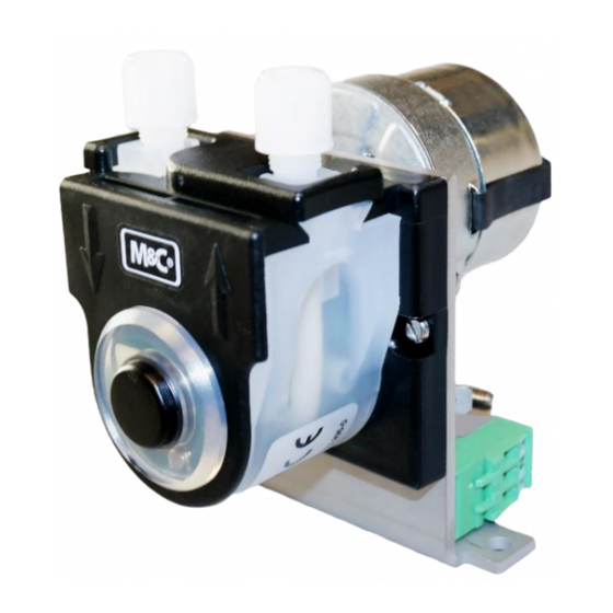
9 DESCRIPTION Check the compatibility of the tube material with unknown gases before using the peristaltic pump. Note The peristaltic pump SR25.X-X is self-suctioning and designed for continuous operation. It consists of 3 compact components: • synchronous motor, • gearing unit with return stop and •... -
Page 11: Figure 2 Drilling Pattern For Sr25.X
Figure 2 Drilling pattern for SR25.X Metric dimensions (mm) are rounded. Inch dimensions are for reference only. In case of doubt or conflict, metric units take priority. Figure 3 Dimensions SR25.X-W www.mc-techgroup.com SR25.X-X | 1.01.01... -
Page 12: Reception And Storage
Metric dimensions (mm) are rounded. Inch dimensions are for reference only. In case of doubt or conflict, metric units take priority. Figure 4 Dimensions SR25.X-G 10 RECEPTION AND STORAGE The peristaltic pump is a complete pre-installed unit. • Please remove the peristaltic pump carefully from the packaging. Check the scope of the delivery specified on the delivery note. -
Page 13: Installation Instructions
11 INSTALLATION INSTRUCTIONS When installing the pump make sure that accident prevention regulations and safety instructions including those for subsequent operation are observed. The safety instructions in section must be observed. The following ambient conditions must be observed: • Ambient temperature during operation: max. +50 °C [122 °F] •... -
Page 14: Supply Connections
Pump head [outside the cooler housing) Cooler front panel Recommended monting distance Pump motor (inside the cooler housing) Figure 5 SR25.2: Mounting distance between front panel and pump motor 12 SUPPLY CONNECTIONS 12.1 TUBING CONNECTIONS The tube connections are on the upper side of the pump. The standard threaded tube connectors are DN 4/6. -
Page 15: Electrical Connections
The tightness of the connections can only be guaranteed if the connection tubing has a straight rim (hose cutter). Note Aggressive condensate possible! Media residues in tubing! Chemical burns caused by aggressive media possible! Wear protective gloves and protective glasses! Wear proper protective clothing! 12.2 ELECTRICAL CONNECTIONS Connect the cables for the power supply as follows:... -
Page 16: Start-Up
Incorrect system voltage can damage the unit. Before connecting the power supply, make sure that the system voltage corresponds with the voltage shown on the type plate! The supply voltage is only allowed to deviate max. +6% resp. -10% from the Caution specification on the model type plate. -
Page 17: Maintenance
15 MAINTENANCE Before starting any maintenance work, make sure that any work done on the device is in compliance with all relevant regulations and standards. Inhalation hazard possible, if using toxic or asphyxiant gases! Warning Purge peristaltic pump with inert gas or air before opening! If the pump is used for toxic gas or asphyxiant (oxygen-displacing) gas, it needs to be purged with inert gas or air before opening. -
Page 18: Changing The Pump Tubing
15.1 CHANGING THE PUMP TUBING 1 Conveying belt 2 S-bolt 3 Tubing set 4 contact pulley 5 springs Figure 7 Changing the pump tubing For changing the pump tubing please proceed as follows: • Unplug the pump from the mains voltage. The device needs to be voltage free. •... -
Page 19: Changing Contact Pulleys And Springs
15.2 CHANGING CONTACT PULLEYS AND SPRINGS While mounting, make sure that the center of rotation and the driver are aligned. Use genuine spare parts only! Note Follow these instructions to change the contact pulley and springs: • Disconnect the peristaltic pump from power supply; •... -
Page 20: Reassembly Of The Driver
The springs may come in different colorings. This is not a quality impairment. Make sure to use the right spring strength. This can be identified by the spring wire diameter. The ‘standard version for Novoprene pump tubing’ (Part No. Note 90P1010) has a diameter of 1.1 mm and the ‘reinforced version for FPM-, Acidflex- or Masterflex-tubing’... -
Page 21: Cleaning The Pump Head
15.3 CLEANING THE PUMP HEAD • When changing flexible tube or other parts, inspect all parts for dirt before assembling the pump head and clean them if necessary. • We recommend to clean the parts with a dry cloth. Solvent should not be used, because it can damage the plastics and synthetic rubber parts. -
Page 22: Spare Parts List
17 SPARE PARTS LIST Wear, tear and replacement part requirements depend on specific operating conditions. The recommended quantities are based on experience and they are not binding. Peristaltic pump SR25.X-X (C) Consumable parts (R) Recommended spare parts (S) Spare parts Recommended quantity being in operation [years] Part No. -
Page 23: Figure 11 Spare Parts (Drawing No.: 2435-1.07.0)
Figure 11 Spare parts (Drawing No.: 2435-1.07.0) www.mc-techgroup.com SR25.X-X | 1.01.01...
Need help?
Do you have a question about the SR Series and is the answer not in the manual?
Questions and answers