Advertisement
Quick Links
FORKLIFT SAFETY
CONTENTS
MANITOU NORTH AMERICA, INC.
6401 IMPERIAL DRIVE
WACO, TX 76712-6803
For Parts Orders contact your Manitou North America Dealer or call:
Manitou North America, Inc. Parts Dept. (800) 425-3727 or (254) 799-0232
Parts Dept. Fax (254) 867-6504 Website: www.manitou-na.com
CALIFORNIA PROPOSITION 65 WARNING
Diesel Engine Exhaust and some of its constituents are known to the State of
California to cause cancer, birth defects or other reproductive harm.
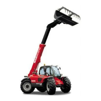
MLT629T Series A
MLT633TLS Series A
MLT730TW(120)LS Series A
MT732T Series A
MT932 Series A
OPERATOR'S MANUAL
THIS OPERATOR'S MANUAL MUST BE KEPT IN THE LIFT TRUCK AND MUST BE READ AND
UNDERSTOOD BY USERS.
547785AS
R/11-10
Advertisement


Need help?
Do you have a question about the A Series and is the answer not in the manual?
Questions and answers