Table of Contents
Advertisement
Quick Links
44158 ANCENIS CEDEX - FRANCE
THIS OPERATOR'S MANUAL MUST BE KEPT IN THE LIFT TRUCK AND MUST BE READ AND UNDERSTOOD BY OPERATORS.
MANITOU BF
BP 10249
TEL: + 33 (0)2 40 09 10 11
YOUR DEALER
647448 EN (20/05/2015)
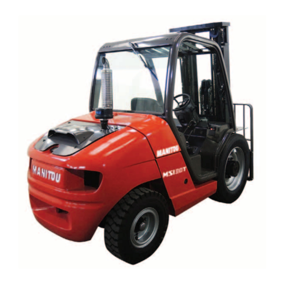
MSI20 T 4ST3B
MSI25 T 4ST3B
MSI30 T 4ST3B
MSI35 T 4ST3B
MH20-4 T BUGGIE 4ST3B
MH25-4 T BUGGIE 4ST3B
OPERATOR'S MANUAL
Advertisement
Chapters
Table of Contents


Need help?
Do you have a question about the MSI20 T 4ST3B and is the answer not in the manual?
Questions and answers