Table of Contents
Advertisement
Quick Links
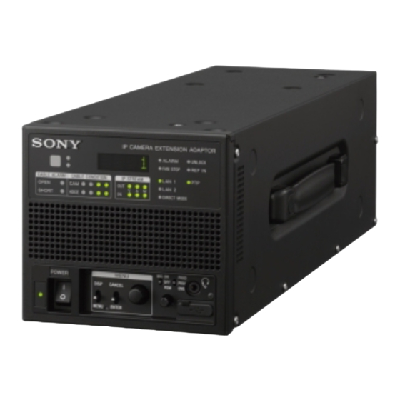
IP CAMERA EXTENSION ADAPTOR
HDCE-TX30
利用条件:
① 本情報はソニー製品の販売、設置、設定、使用の目的でのみご利用ください。かかる目的以外での利用を禁止します。
② 著作者の事前の書面による許可なく、本情報の全部または一部の複写、複製、転載、改変、翻訳、送信等を禁止します。
情報改訂:
本情報は、当社の裁量により、予告なく変更されることがあります。ご使用される場合、本情報が最新の情報であることを確認のうえ、
ご使用ください。
Conditions of Use:
(1) Please use this information only for the purpose of sales, installation, configuration, and use of Sony products. Using this information
for any purpose other than the purpose described foregoing is forbidden.
(2) Do not copy, replicate, reproduce, alter, translate, transmit, sell, lease, or distribute this information in whole or in part without the prior
written permission of the author.
Revision of Information:
This information may be changed or updated at any time without any prior notice. Please confirm that this information is up-to-date before
using it.
SERVICE MANUAL
1st Edition
Advertisement
Table of Contents

Related Manuals for Sony HDCE-TX30


Summary of Contents for Sony HDCE-TX30
- Page 1 ご使用ください。 Conditions of Use: (1) Please use this information only for the purpose of sales, installation, configuration, and use of Sony products. Using this information for any purpose other than the purpose described foregoing is forbidden. (2) Do not copy, replicate, reproduce, alter, translate, transmit, sell, lease, or distribute this information in whole or in part without the prior written permission of the author.
- Page 2 à moins d’être qualifié pour en effectuer d’autres. Pour toute réparation faire appel à une personne compétente uniquement. Model Name Serial No. HDCE-TX30/L (SY): LEMO Optical Fiber Connector 10001 and Higher HDCE-TX30/T (E): Tajimi Optical Fiber Connector 30001 and Higher 安全のために,周辺機器を接続する際は,過大電圧を...
- Page 3 注意 感電の危険があります。 本製品の一次回路のヒューズが,中性線側に接続さ れる可能性があります。 修理時の感電を防ぐため,本機を主電源から切り離 してください。 CAUTION RISK OF ELECTRIC SHOCK The fuse of the primary circuit of this product may be connected on the neutral wire side. Disconnect the unit from the power supply to prevent electric shock when repairing. ATTENTION RISQUE D’ÉLECTROCUTION Le fusible du circuit primaire de ce produit peut être...
- Page 4 注意 FÖRSIKTIGHET! 指定以外の電池に交換すると,破裂する危険があり Fara för explosion vid felaktigt placerat batteri. ます。 Byt endast mot samma eller likvärdig typ av batteri, 必ず指定の電池に交換してください。 enligt tillverkarens rekommendationer. 使用済みの電池は,国または地域の法令に従って När du kasserar batteriet ska du följa rådande lagar 処理してください。 för regionen eller landet. CAUTION PAS PÅ...
-
Page 5: Table Of Contents
Table of Contents Section 1 Service Overview.................................. 4 1-1. Location of Printed Wiring Boards ............................... 4 1-2. Functions of Onboard Switches and LED Indicators ........................5 1-2-1. NET-37 Board ..................................5 1-2-2. VIF-82 Board ..................................7 1-3. Notes on Replacement of Circuit Board ............................8 1-3-1. - Page 6 2-5. VIF-82 Board Assembly ................................38 2-5-1. VIF-82 Board/AT-195 Board ..............................40 2-5-2. Coaxial Connector Converter (BNC Type) .......................... 44 2-6. Lithium Battery ................................... 47 2-7. Optical Multi Fiber Cables................................48 2-7-1. LEMO Connector Assembly ..............................48 2-7-2. TAJIMI Connector Assembly ............................... 50 2-8.
- Page 7 Section 6 Spare Parts ..................................81 6-1. Note on Repair Parts ................................... 81 6-2. Exploded Views ..................................82 Cover ......................................82 NET-37 Board ....................................83 Front Panel ..................................... 84 VIF-82 Board ....................................85 DC Fans ......................................86 Chassis ......................................87 Power Block ....................................
-
Page 8: Section 1 Service Overview
Section 1 Service Overview 1-1. Location of Printed Wiring Boards CN-4132 CN-4131 RE-345 PS-939 LE-436 NET-37 AT-195 LE-437 VIF-82 FP-322 SW-1775... -
Page 9: Functions Of Onboard Switches And Led Indicators
1-2. Functions of Onboard Switches and LED Indicators 1-2-1. NET-37 Board S0401 D1201 S1101 S0601 NET-37 Board (Side A) Switch Note Do not change the setting of “Factory use” switch. Ref. No. Name Function Factory default setting - S0401 Factory use -... - Page 10 Ref. No. Name Color Description Normal State (Power On) D0201 TDIS_A Factory use Inconstant D0202 TFAULT_A Factory use Inconstant D0203 MOD ABS_A Factory use Inconstant D0204 RX_LOS_A Factory use Inconstant D0205 TDIS_B Factory use Inconstant D0206 TFAULT_B Factory use Inconstant D0207 MOD ABS_B Factory use...
-
Page 11: Vif-82 Board
1-2-2. VIF-82 Board S1401 S1101 VIF-82 Board (Side A) VIF-82 Board (Side B) Switch Note Do not change the setting of “Factory use” switch. Ref. No. Name Description Factory default setting S1101 DebugSW 1 to 4 For debugging IC1101 OFF (ALL) S1401 DebugSW 1 to 4... -
Page 12: Notes On Replacement Of Circuit Board
1-3. Notes on Replacement of Circuit Board 1-3-1. AT-195 Board, VIF-82 Board and Power Unit (RE-345 Board) AT-195 board, VIF-82 board, and RE-345 board store the important information including the model name and serial number. After replacing the AT-195 board, VIF-82 board, and RE-345 board, perform RESTORE on the [04 <SERIAL NUMBER>] page of the SERVICE menu. -
Page 13: Cautions When Replacing The Lithium Battery
1-4. Cautions when Replacing the Lithium Battery The lithium battery is installed on the VIF-82 board. This lithium battery is used to back up the real-time clock (RTC). RTC stops operating when the battery life expires. Replace the battery and reset the DATE & TIME (M03) of the MAINTENANCE menu. -
Page 14: Cleaning Of Connector/Cable
1-5. Cleaning of Connector/Cable • Lit in two green indicators (right): Receive signal condition is very good. • Lit in one green indicator (2nd from right): Receive signal condition is OK. • Lit in one yellow indicator (2nd from left): Receive signal level is weak. •... -
Page 15: When The Optical Connector Cleaner (Commercially Available) Is Not Available (Connectors/Cables Of Lemo)
Fixtures • Alignment sleeve remover HC-001 (for female connector) Sony Part No.: J-6480-010-A or DCC.91.312.5LA manufactured by LEMO, or equivalent Note Insert the shorter nose end when removing/installing the alignment sleeve. This fixture contains shock absorber portion. Grasp not the shock absorber portion of the remover but the handle in use. -
Page 16: When The Optical Connector Cleaner (Commercially Available) Is Not Available
The alignment sleeve can be removed/reinstalled with the sleeve itself attached to the tip of the remover. Great care should be taken so as not to lose or damage the alignment sleeve. Alignment sleeve: Sony Part No.: 9-980-074-01 Alignment sleeve Clean the tip of the optical contacts (white) with a cotton swab moistened with alcohol. - Page 17 Pull the adapter pin out of the connector in the arrow direction. Remove the adapter from the connector. Adapter Adapter pin Clean the optical contacts (white) with a cotton swab moistened with alcohol. Optical contacts (white) Match the positioning marks of the adapter and the connector, and then push the adapter into the connector. Note Push the adapter until the confirmation groove comes in sight as shown in the figure.
-
Page 18: When The Optical Connector Cleaner (Commercially Available) Is Not Available (Connector)
1-5-4. When the Optical Connector Cleaner (Commercially Available) is not Available (Connector) Fixtures • Alcohol (commercially available) • Cotton swabs (commercially available) Note Use a cotton swab whose diameter is about 4 mm. If a cotton swab whose diameter exceeds 5 mm is used, the cotton swab cannot be inserted into the end of the connector and the tip of the optical contact cannot be cleaned. -
Page 19: Pld
This unit uses the PLD (Programmable Logic Device) that supports USB drive to write and rewrite the internal data. If the part listed below needs to be replaced or to be upgraded, contact your local Sony Sales Office/Service Center. Note The part number of PLD (or ROM for PLD) in which data is not written yet, is shown in “Spare Parts”. -
Page 20: Flexible Flat Cable And Coaxial Cable
1-8. Flexible Flat Cable and Coaxial Cable 1-8-1. Disconnecting/Connecting Flexible Flat Cable Note • Be very careful not to fold flexible flat cables. Life of flexible flat cable will be significantly shortened if it is folded. • Each flexible flat cable has conductive side and insulated side. If the flexible flat cable is connected in the wrong orientation of the conductive side and the insulated side, the circuit will not function. -
Page 21: Disconnecting/Connecting Fine-Wire Coaxial Cable
Connecting Latch Connector Flexible card wire Insulated side Insert the flexible flat cable firmly as far as it will go with the insulated side up. Close the latch of the connector in the direction of arrow B to lock the flexible flat cable. 1-8-2. - Page 22 Type B Disconnecting Pull-bar Correct Hold the connector to disconnect. Fine-wire coaxial cable Connector Wrong Do not attempt to disconnect by pulling the cable. Raise the pull-bar in the direction of arrow A to unlock it. Hold both sides of the fine-wire coaxial cable connector, and pull the connector straight to disconnect it. Connecting Angle regulation Pull-bar...
- Page 23 Type C Disconnecting Both sides of connector Hold the connector to disconnect. Correct Do not attempt to disconnect by Fine-wire coaxial cable Wrong pulling the cable. Hold both sides of the fine-wire coaxial cable connector, and pull the connector portion of the fine-wire coaxial cable in the direction of the arrow to disconnect it.
-
Page 24: Connecting/Disconnecting Coaxial Cable
1-8-3. Connecting/Disconnecting Coaxial Cable Type A Disconnecting Correct Wrong Hold the plug to remove. Do not attempt to remove by pulling the cable. Hold the plug of coaxial cable. Pull out the coaxial cable in the direction of the arrow. Note Be sure to hold the plug when disconnecting the coaxial cable. -
Page 25: Circuit Protective Devices
The fuse is critical parts to safe operation. Replace the components with Sony parts whose part number appear in the manual published by Sony. If the components are replaced by any parts other than the specified ones, this may cause a fire or electric shock. -
Page 26: Section 2 Replacement Of Main Parts
Section 2 Replacement of Main Parts 2-1. Notes on Replacing the Parts 2-1-1. Tightening Torque Torque driver and screw tightening torque General screws are used in this unit. Be sure to use a torque driver and tighten screws to the specified tightening torque. B2 x 5: 0.19 ±0.12 N·m B3 x 5: 0.80 ±0.12 N·m K2.6 x 6: 0.53 ±0.07 N·m... -
Page 27: Top Cover
2-2. Top Cover Procedure Remove the seven screws. B3 x 5 Note When attaching the top cover, tighten the screws (a) to (g) sequentially in alphabetical order. - Page 28 Remove the 12 screws, and then remove the top cover. When removing the top cover, slightly extend it in the directions of the arrows (A). B3 x 5 Top cover B3 x 5 B3 x 5 Directions to press the top cover during installation B3 x 5 Top cover B3 x 5...
-
Page 29: Net-37 Board Assembly
2-3. NET-37 Board Assembly Preparation Remove the top cover. (Refer to “2-2. Top Cover”.) Procedure Release the cables from the three cable clamps and the four locking edge saddles. Disconnect the fine-wire coaxial cable (blue) from the connector (CN0104) on the NET-37 board. Disconnect the two fine-wire coaxial cables and the four harnesses from the connectors (CN001, CN301, CN307, CN402, CN404, CN601) on the VIF-82 board. - Page 30 Release the two fine-wire coaxial cables and the harness from the cable clamps. Disconnect the two fine-wire coaxial cables and the harness from the connectors (CN0101, C0102, CN0103) on the NET-37 board. NET-37 board CN0103 Cable clamps CN0101 CN0102 Harness Fine-wire coaxial cables Arrangement of the cables NET-37 board...
- Page 31 Remove the four screws, and then remove the top chassis. Top chassis 3 x 8 Hole Projection Boss Hole Remove the six screws, and then remove the NET-37 board assembly in the direction of the arrow. 3 x 8 NET-37 board assembly 3 x 8 Note At the time of the installation, tighten the screws in the following sequence: (a), (b), (c), (d).
-
Page 32: Net-37 Board
2-3-1. NET-37 Board Preparation Remove the top cover. (Refer to “2-2. Top Cover”.) Remove the NET-37 board assembly. (Refer to “2-3. NET-37 Board Assembly”.) Procedure Remove the three screws. Remove the NET heat sink B in the direction of the arrow [A]. Projection Radiation sheet (DPRH) NET heat sink B... - Page 33 Remove the five screws. Remove the NET-37 board in the direction of the arrow [A]. Connectors 3 x 8 NET-37 board Holes Radiation sheet (2(35 x 35)) NET heat sink A Attaching position of the radiation sheet (2(35 x 35)) Scribe lines NET heat sink A Radiation sheet (2(35 x 35))
-
Page 34: Front Panel Assembly
2-4. Front Panel Assembly Preparation Remove the top cover. (Refer to “2-2. Top Cover”.) Remove the NET-37 board assembly. (Refer to “2-3. NET-37 Board Assembly”.) Procedure Disconnect the flexible flat cable from the connector (CN401) on the VIF-82 board. Release the flexible flat cable from the two cable clamps. Remove the screw, and then remove the front panel assembly. -
Page 35: Le-436 Board
2-4-1. LE-436 Board Preparation Remove the top cover. (Refer to “2-2. Top Cover”.) Remove the NET-37 board assembly. (Refer to “2-3. NET-37 Board Assembly”.) Remove the front panel assembly. (Refer to “2-4. Front Panel Assembly”.) Procedure Disconnect the two harnesses from the connectors (CN001, CN002) on the LE-436 board. Remove the four screws, and then remove the LE-436 board. -
Page 36: Fp-322 Board
2-4-2. FP-322 Board Preparation Remove the top cover. (Refer to “2-2. Top Cover”.) Remove the NET-37 board assembly. (Refer to “2-3. NET-37 Board Assembly”.) Remove the front panel assembly. (Refer to “2-4. Front Panel Assembly”.) Procedure Remove the rotary encoder knob. Remove the three screws, and then remove the FP-322 board. - Page 37 Disconnect the flexible flat cable from the connector (CN001) on the FP-322 board. Remove the EP cushion (L) and the EP cushion (B). EP cushion (L) EP cushion (B) *soft CN001 FP-322 board Flexible flat cable Note At the time of the installation, attach the soft EP cushion (B), and then attach the EP cushion (L). Install the removed parts by reversing the steps of removal.
-
Page 38: Le-437 Board
2-4-3. LE-437 Board Preparation Remove the top cover. (Refer to “2-2. Top Cover”.) Remove the NET-37 board assembly. (Refer to “2-3. NET-37 Board Assembly”.) Remove the front panel assembly. (Refer to “2-4. Front Panel Assembly”.) Procedure Disconnect the harness from the connector (CN001) on the LE-437 board. Remove the screw, and then remove the LE-437 board. -
Page 39: Sw-1775 Board
2-4-4. SW-1775 Board Preparation Remove the top cover. (Refer to “2-2. Top Cover”.) Remove the NET-37 board assembly. (Refer to “2-3. NET-37 Board Assembly”.) Remove the front panel assembly. (Refer to “2-4. Front Panel Assembly”.) Remove the FP-322 board. (Refer to “2-4-2. FP-322 Board”.) Procedure Remove the screw, and then remove the SW-1775 board. -
Page 40: Filter
2-4-5. Filter Preparation Remove the top cover. (Refer to “2-2. Top Cover”.) Remove the NET-37 board assembly. (Refer to “2-3. NET-37 Board Assembly”.) Remove the front panel assembly. (Refer to “2-4. Front Panel Assembly”.) Remove the LE-436 board. (Refer to “2-4-1. LE-436 Board”.) Procedure Remove the cushion (T). - Page 41 Lift one side of the filter holder as shown below. Remove the filter. Filter holder Filter Front cover Inserting the filter holder (cross-sectional view) Direction to push the filter at the time of the installation Filter Filter holder Front cover Filter holder Check that the filter holder is installed under the front cover before inserting the filter.
-
Page 42: Vif-82 Board Assembly
2-5. VIF-82 Board Assembly Preparation Remove the top cover. (Refer to “2-2. Top Cover”.) Remove the NET-37 board assembly. (Refer to “2-3. NET-37 Board Assembly”.) Procedure Disconnect the optical fiber cables from the optical module (SFP+). Note • Do not pull the optical fiber cables strongly or bend them so as not to damage them. •... - Page 43 Release the harness (a) from the cable clamp (a), and then disconnect the harness (a) from the connector (CN303) on the VIF-82 board. Release the harness (b) from the cable clamp (b), and then disconnect the harness (b) from the connector (CN302) on the VIF-82 board.
- Page 44 2-5-1. VIF-82 Board/AT-195 Board Preparation Remove the top cover. (Refer to “2-2. Top Cover”.) Remove the NET-37 board assembly. (Refer to “2-3. NET-37 Board Assembly”.) Remove the VIF-82 board assembly. (Refer to “2-5. VIF-82 Board Assembly”.) Procedure Release the two fine-wire coaxial cables from the three clamps. Disconnect the two fine-wire coaxial cables from the connectors (CN305, CN306) on the VIF-82 board.
- Page 45 Release the harness from the two cable clamps. Disconnect the harness from the connector (CN304) on the VIF-82 board. Disconnect the three coaxial cables from the connectors (J801, J1701, J1702) on the VIF-82 board. J1701 J1702 J801 Cable clamps VIF-82 board Coaxial cable (orange) CN304 Coaxial cable (green)
-
Page 46: Vif-82 Board/At-195 Board
Remove the two screws, and then remove the rear connector block. P2.6 x 5 Rear connector block Locking compound application area Locking compound 1401B (Size of a grain of rice) Note At the time of the installation, apply locking compound shown in the figure. Remove the two screws, and then remove the AT-195 board. - Page 47 Remove the six screws, and then remove the VIF heat sink (B) and the radiation sheet (DPRH). Attaching position of the radiation sheet (DPRH) 3 x 8 VIF heat sink (B) Hole 3 x 8 Hole Radiation sheet (DPRH) Radiation sheet Projection (DPRH) Line...
-
Page 48: Coaxial Connector Converter (Bnc Type)
2-5-2. Coaxial Connector Converter (BNC Type) Preparation Remove the top cover. (Refer to “2-2. Top Cover”.) Remove the NET-37 board assembly. (Refer to “2-3. NET-37 Board Assembly”.) Remove the VIF-82 board assembly. (Refer to “2-5. VIF-82 Board Assembly”.) Remove the rear connector block. (Refer to steps 1 to 6 in “2-5-1. VIF-82 Board/AT-195 Board”.) Procedure Release the three coaxial cables from the BNC coaxial fixed washers. - Page 49 Remove the two screws, and then remove the CN-4131 board. Disconnect the harness from the connector (CN001) on the CN-4131 board. P2.6 x 5 Harness CN001 CN-4131 board Remove the three supplied nuts, and then remove the three BNC coaxial fixed washers and the three BNC coaxial connector converters (BNC type).
- Page 50 Remove the supplied nut with the new coaxial connector converter (BNC type) and discard the supplied star washer. Coaxial connector converter (BNC type) Supplied star washer Supplied nut Install the removed parts by reversing the steps of removal. Note • Before installing the supplied nut, apply locking compound.
-
Page 51: Lithium Battery
2-6. Lithium Battery Preparation Remove the top cover. (Refer to “2-2. Top Cover”.) Procedure Remove the lithium battery from the four hooks of the battery holder. Hooks Lithium Battery Lithium Battery Battery holder Hooks VIF-82 board Note When installing the lithium battery, install it to the orientation shown in the figure. Install the removed parts by reversing the steps of removal. -
Page 52: Optical Multi Fiber Cables
2-7. Optical Multi Fiber Cables Note Do not pull the optical fiber cables strongly or bend them so as not to damage them. 2-7-1. LEMO Connector Assembly Preparation Remove the top cover. (Refer to “2-2. Top Cover”.) Procedure Release the harness and the two optical fiber cables from the two locking edge saddles and the two clamps. Disconnect the two optical fiber cables from the optical module (SFP+). - Page 53 Disconnect the harness from the connector (CN5004) on the RE-345 board. Remove the four screws, and then remove the LEMO connector assembly Remove the four screws, and then remove the lug terminal and LEMO CN bracket. Harness RE-345 board Rear panel assembly LEMO CN bracket 3 x 8 Front side...
-
Page 54: Tajimi Connector Assembly
2-7-2. TAJIMI Connector Assembly Preparation Remove the top cover. (Refer to “2-2. Top Cover”.) Remove the optical fiber cable. (Refer to steps 1 to 3 in “2-7-1. LEMO Connector Assembly”.) Procedure Disconnect the harness from the connector (CN5004) on the RE-345 board. Remove the four screws, and then remove the TAJIMI connector assembly. -
Page 55: Cn-4132 Board
2-8. CN-4132 Board Preparation Remove the top cover. (Refer to “2-2. Top Cover”.) Remove the optical multi fiber cable. (Refer to “2-7. Optical Multi Fiber Cable”.) Procedure Disconnect the fine-wire coaxial cable from the connector (CN001) on the CN-4132 board. Remove the two screws, and then remove the CN-4132 board. -
Page 56: Dc Fan (60 X 15)
2-9. DC Fan (60 x 15) The following part cannot be reused. When replacing the DC fan (60 x 15), use the new one. • Fan cushion Preparation Remove the top cover. (Refer to “2-2. Top Cover”.) Remove the optical multi fiber cable. (Refer to “2-7. Optical Multi Fiber Cables”.) Remove the CN-4132 board. - Page 57 Remove the DC fan subassembly from the power fan mounting bracket. Harness Label DC fan subassembly Power fan mounting bracket Note When attaching the DC fan subassembly, pay attention to the position of label and harness. Remove the two fan cushions from the DC fan (60 x 15). Attaching position of the fan cushion DC fan (60 x 15) Harness...
-
Page 58: Ac Inlet
2-10. AC Inlet Preparation Remove the top cover. (Refer to “2-2. Top Cover”.) Remove the optical multi fiber cable. (Refer to “2-7. Optical Multi Fiber Cables”.) Remove the CN-4132 board. (Refer to “2-8. CN-4132 Board”.) Remove the DC fan subassembly. (Refer to “2-9. DC Fan (60 x 15)”.) Procedure Remove the two screws, and then remove the power fan mounting bracket. - Page 59 Disconnect the AC-IN harness from the connector (CN102) on the PS-939 board. Remove the screw (PSW4 x 8), and then remove the earth lug terminal Remove the two screws (PSW3 x 10), and then remove the plug holder (A) Pull out the AC inlet from the hole of the rear panel. Disconnect the AC harness and earth harness from the AC inlet.
-
Page 60: Dc Fan (60 Square) (Front)
2-11. DC Fan (60 Square) (Front) The following part cannot be reused. When replacing the DC fan (60 square). • Fan cushion (60 x 25) Preparation Remove the top cover. (Refer to “2-2. Top Cover”.) Remove the NET-37 board assembly. (Refer to “2-3. NET-37 Board Assembly”.) Procedure Disconnect the flexible flat cable from the connector (CN401) on the VIF-82 board. - Page 61 Remove the DC fan (60 square) and the fan cushion (60 x 25) together from the F-fan mounting bracket. Remove the two fan cushions (60 x 25) from the DC fan (60 square). Fan cushion (60 x 25) Attaching position of the fan cushion (60 x 25) Fan cushion (60 x 25) Harness DC fan (60 square)
-
Page 62: Dc Fan (60 Square) (Rear)
2-12. DC Fan (60 Square) (Rear) The following part cannot be reused. When replacing the DC fan (60 square). • Fan cushion (60 x 25) Preparation Remove the top cover. (Refer to “2-2. Top Cover”.) Remove the NET-37 board assembly. (Refer to “2-3. NET-37 Board Assembly”.) Remove the VIF-82 board assembly. - Page 63 Remove the DC fan (60 square) and the fan cushion (60 x 25) together from the R-fan mounting bracket. Remove the two fan cushions (60 x 25) from the DC fan (60 square). Hole R-fan mounting bracket Attaching position of the fan cushion (60 x 25) Fan cushion (60 x 25) Fan cushion (60 x 25) DC fan (60 square)
-
Page 64: Power Block
2-13. Power Block The following part cannot be reused. When replacing the power block. • Power duct sheet Preparation Remove the top cover. (Refer to “2-2. Top Cover”.) Remove the NET-37 board assembly. (Refer to “2-3. NET-37 Board Assembly”.) Remove the front panel assembly. (Refer to “2-4. Front Panel Assembly”.) Remove the VIF-82 board assembly. - Page 65 Release the harness from the cable clamp, and then disconnect the harness from the connector (CN1006) on the PS-939 board. Remove the three screws, and then remove the power switch sub assembly. Remove the power block. 3 x 8 Power block CN1006 (PS-939 board) 3 x 8...
- Page 66 Disconnect the harness from the connector (CN5003) on the RE-345 board. Remove the clamp, the two cable clamps and the power duct sheet. Clamp Power block Cable clamp CN5003 (RE-345 board) Cable clamp Harness Power duct sheet Attaching position of the power duct sheet Power duct sheet Plate When replacing the power block, attach new power duct sheet at the positions shown above.
-
Page 67: Re-345 Board
2-13-1. RE-345 Board Preparation Remove the top cover. (Refer to “2-2. Top Cover”.) Remove the NET-37 board assembly. (Refer to “2-3. NET-37 Board Assembly”.) Remove the front panel assembly. (Refer to “2-4. Front Panel Assembly”.) Remove the VIF-82 board assembly. (Refer to “2-5. VIF-82 Board Assembly”.) Remove the optical multi fiber cable. - Page 68 Remove the seven screws, and then remove the RE-345 board. 3 x 6 RE-345 board Radiation sheets (H) Insulating sheet (PS-B) Top case (PS) Marks Note When replacing the radiation sheets (H), attach them on the insulating sheet (PS-B) according to the marks in the top case (PS). Install the removed parts by reversing the steps of removal.
-
Page 69: Dc Fan (Power)
2-13-2. DC Fan (Power) Preparation Remove the top cover. (Refer to “2-2. Top Cover”.) Remove the NET-37 board assembly. (Refer to “2-3. NET-37 Board Assembly”.) Remove the front panel assembly. (Refer to “2-4. Front Panel Assembly”.) Remove the VIF-82 board assembly. (Refer to “2-5. VIF-82 Board Assembly”.) Remove the optical multi fiber cable. -
Page 70: Ps-939 Board
2-13-3. PS-939 Board Preparation Remove the top cover. (Refer to “2-2. Top Cover”.) Remove the NET-37 board assembly. (Refer to “2-3. NET-37 Board Assembly”.) Remove the front panel assembly. (Refer to “2-4. Front Panel Assembly”.) Remove the VIF-82 board assembly. (Refer to “2-5. VIF-82 Board Assembly”.) Remove the optical multi fiber cable. -
Page 71: Section 3 Software Update
Copy the camera application update data to the USB drive using the following procedure. Note For how to obtain the data file for update (hdcetx50_app.pkg), contact your local Sony Sales Office/Service Center. Create the following directory in the USB drive. -
Page 72: Upgrading Update Software
Copy the OS update data to the USB drive using the following procedure. Note For how to obtain the data file for update (hdcetx50_os.pkg), contact your local Sony Sales Office/Service Center. Create the following directory in the USB drive. \MSSONY\PRO\CAMERA\HDCETX50 Copy the data file for update “hdcetx50_os.pkg”... -
Page 73: Forced Version Update
Preparation Copy the PLD update data to the USB drive using the following procedure. Note For how to obtain the data files for update, contact your local Sony Sales Office/Service Center. Create the following directory in the USB drive. \MSSONY\PRO\CAMERA\HDCETX50 Copy the data file for update to be updated to the directory created. -
Page 74: Section 4 Menu Settings
Section 4 Menu Settings This unit can display the unit status and entire system status on the monitor connected to the SDI output connectors to check or change settings. 4-1. Preparations 4-1-1. Display/Hide the Status Screen To display the status screen Turn the DISP/MENU lever to the DISP side. -
Page 75: Changing Setting Values
Exiting When the status screen or menu screen is displayed, hide the screen. Turn the CANCEL/ENTER lever quickly to the CANCEL side twice. 4-1-3. Changing Setting Values To enter: Press the control knob. Or turn the CANCEL/ENTER lever to the ENTER side. To cancel: Turn the CANCEL/ENTER lever to the CANCEL side before pressing the control knob. -
Page 76: Service Menu
4-2. SERVICE Menu This unit is provided with the SERVICE menu useful for maintenance. For how to display the SERVICE menu, refer to “4-1-2. Starting and Exiting the SERVICE Menu”. 4-2-1. SERVICE Menu List Screen display CONTENTS ?S00 TOP 01 <SOFTWARE PACKAGE> 02 <PLD PACKAGE>... -
Page 77: Description Of Service Menu
4-2-2. Description of SERVICE Menu The display screen appearing in this section shows the indication example. SOFTWARE PACKAGE Screen display <SOFTWARE PACKAGE> ?S01 TOP APPLICATION : V1.00 V1.00 UPDATER V1.00 Description Item Setting Value Description - APPLICATION Display the current software version. Place the cursor on the version to update the version. - Page 78 Reset the cumulative power-on time. - REGENERATE UUID Regenerate the UUID. SERIAL NUMBER Screen display <SERIAL NUMBER> ?S04 TOP MODEL NAME : HDCE-TX30 SERIAL NUMBER: 01234567 ?RESTORE Description Item Setting Value Description MODEL NAME HDCE-xxxx Display the model name of the unit.
- Page 79 POWER UNIT Screen display <POWER UNIT> ?S05 TOP OUTPUT CAMERA :123.45V 1.23A 123.45W :123.45V 0.36A 123.45W :123.45V 0.36A 123.45W :123.45V 0.36A 123.45W SY PLD : 13.88V 3.43A 47.69W VIF PLD: 14.32V 0.00A 0.04W INPUT POWER :123.45V TEMPERATURE :555.2 CAM POWER REMOTE : NORMAL Description Item Setting Value...
- Page 80 MODE Screen display <MODE> ?S06 TOP MEDIA CLOCK DIRECT AUDIO : 0.000ms HD TRUNK AUDIO : 0.000ms INTERCOM : 0.000ms TEST OUT : IP RETURN IP LOOPBACK : EXEC Description Item Setting Value Description - MEDIA CLOCK DIRECT Set the Media Clock Direct value to be sent using the SAP protocol for each IP Audio stream.
- Page 81 TEMPERATURE Screen display <TEMPERATURE> ?S07 TOP VIF FPGA(ON BOARD) : 33.0 VIF FPGA(INTERNAL) : 39.0 NET FPGA(INTERNAL) : 42.0 POWER UNIT : 28.0 Description Item Setting Value Description - VIF FPGA (ON BOARD) Display the temperature of VIF-82 board. VIF FPGA (INTERNAL) -...
-
Page 82: Section 5 Circuit Description
Section 5 Circuit Description 5-1. Circuit Description of Each Board 5-1-1. AT-195 Board The AT-195 board consists of a system control microcomputer (IC001) and a peripheral circuit. The main program is stored in the flash memory (IC401) on the AT-195 board. This board is connected to the VIF-82 board. -
Page 83: Vif-82 Board
5-1-9. VIF-82 Board Main-line video signals The image capture data transmitted from the camera is converted to 8b10b data, and is then input to the VIF-82 board through the connector (CN403). The VIF-82 board performs video format conversion for the three SDI output signals. Four DDR3 SDRAM ICs (IC1901, IC1902, IC1903, and IC1904) are connected to IC1401. - Page 84 NETWORK TRUNK signal The NETWORK TRUNK signal from the RJ-45 connector on the CN-4132 board is input from the connector (CN601) to IC601 in which the signal format is converted. Then the converted signal is input to IC1101. Packet data that passes this connector can be included in the Link-B data of the serial digital video signal, enabling transmission and reception of the NETWORK TRUNK packet to/from the camera.
-
Page 85: Section 6 Spare Parts
Therefore, specified parts should be used in the case 指定の部品を使ってください。 of replacement. 2. 部品の共通化 2. Standardization of Parts ソニーから供給する補修用部品は,セットに使われ Some repair parts supplied by Sony differ from those ているものと異なることがあります。 used for the unit. These are because of parts common- これは部品の共通化,改良等によるものです。 ality and improvement. 3. 部品の在庫... -
Page 86: Exploded Views
6-2. Exploded Views Cover K2.6 x 6 P4 x 10 P4 x 10 Refer to “NET-37 Board” Part No. SP Description 1-912-393-11 s CONNECTION CABLE WITH COAXIAL 2-382-110-01 o LEG 3-725-295-21 s SCREW, (+) (B3) 3-815-708-01 s HANDLE 4-098-033-01 s SADDLE WIRE (C) 4-382-854-01 s SCREW (M3X8), P, SW (+) 4-641-552-01 o SADDLE, LOCK EDGE 5-010-134-01 s TOP COVER... -
Page 87: Net-37 Board
NET-37 Board Refer to “VIF-82 Board” Refer to “DC Fans” Refer to “Front Panel” Part No. SP Description A-5022-883-A s NET-37C COMPL 4-098-033-01 s SADDLE WIRE (C) 4-382-854-01 s SCREW (M3X8), P, SW (+) 4-559-446-02 s SCREW, +P2.6X5 NEW TRUSTER 4-581-951-01 s CAGE, SINGLE PORT 4-587-426-01 s SHEET (2 (35X35)), RADIATION 5-001-322-01 s SHEET (DPRH), RADIATION... -
Page 88: Front Panel
Front Panel To VIF-82 board To VIF-82 board Part No. SP Description A-5010-099-A s FP-322_MOUNT A-5010-100-A s LE-436_MOUNT A-5010-101-A s LE-437_MOUNT A-5011-717-A s SW-1775_MOUNT 1-007-500-11 s FFC 36PIN 160MM 1-970-222-11 s SUB HARNESS(ENC) 1-970-789-11 s HARNESS, SUB (MEM-PWR) 1-971-327-11 s SUB HARNESS BF-PP_MOTOR 3-906-254-01 o CLAMP 4-139-232-01 s KNOB, ROTARY ENCODER 4-170-412-02 s GUIDE, LIGHT... -
Page 89: Vif-82 Board
VIF-82 Board To NET-37 board To NET-37 board Part No. SP Description A-5011-246-A s CN-4131_MOUNT A-5014-715-A s AT-195F_COMPL A-5020-673-A s VIF-82 COMPL 1-001-819-11 s COAXIAL HARNESS(60MM)(YELLOW) 1-510-039-11 s OPTICAL MODULE (1.8725/3.7G) 1-756-134-18 s BATTERY, LITHIUM (SECONDARY) 1-784-240-11 s CONVERTER, COAXIAL CONNECTOR 1-846-804-11 s HARNESS, COAXIAL(85MM)(ORANGE) 1-846-805-11 s HARNESS, COAXIAL(85MM)(GREEN) 1-912-710-11 s MICRO COAXIAL CABLE (CA60 260... -
Page 90: Dc Fans
DC Fans To VIF-82 board To VIF-82 board S/N: 10001 and higher To VIF-82 board To VIF-82 board To VIF-82 board S/N: 30001 and higher To VIF-82 board Refer to “Cassis” Part No. SP Description A-2189-820-A s LEMO CONNECTOR ASSY-A(FXW)EXP A-5010-103-A s CN-4132_MOUNT 1-838-045-12 s OPTICAL MULTI CABLE ASSEMBLY 1-855-432-11 s FAN, DC (60 SQUARE) -
Page 91: Chassis
Chassis Refer to “Power Block” To VIF-82 board PSW4 x 8 PSW3 x 10 To NET-37 board Part No. SP Description 1-007-501-11 s HARNESS, SUB (NET POWER) 1-842-404-11 s AC INLET (SCREW) 3P FASTEN 1-972-256-12 s HARNESS, SUB (POWER SW) 1-972-258-13 s HARNESS, SUB (AC IN) 1-972-259-12 s HARNESS, SUB (EARTH) 1-972-261-11 s HARNESS, SUB (VIF POWER) -
Page 92: Power Block
Power Block To VIF-82 board K3 x 6 K3 x 6 K3 x 6 K3 x 6 K3 x 6 K3 x 6 P2 x 6 K3 x 6 Part No. SP Description A-2218-257-A s RE-345 COMPL A-2218-360-A s PS-939 MOUNT A-5003-492-A s POWER ASSY H 1-855-096-31 s DC FAN 1-972-266-12 s SUB HARNESS AC... -
Page 93: Supplied Accessories
6-3. Supplied Accessories Q'ty Part No. SP Description 5-019-140-01 s CD-ROM PACK... -
Page 94: Section 7 Diagrams
Section 7 Diagrams Overall (1/3) VIF-82(1/2) IC1401(1/2) IC1703 SDI_IO1_RX_P/N J1703 CABLE SDI_IO1_TX_P/N DRIVER SDI I/O 1 EQUALIZER IC1403(1/2),1404(1/2) LMH0397_MOSI LMH0397_SS1_N BUFFER IC1704 SDI_IO2_RX_P/N J1704 CABLE SDI_IO2_TX_P1/N1 DRIVER SDI I/O 2 CN1401 VIF-PLD EQUALIZER IC1403(2/2),1404(2/2) LMH0397_MOSI FPGA2_DBG0-8 LMH0397_SS2_N BUFFER IC1702 CN2001 TDI/TDO/TMS/TCK J1702 SDI_OUT_TX_P/N... -
Page 95: Overall (2/3)
Overall (2/3) AT-195F VIF-82(2/2) FP-322 CN101 CN501 IC001 USB_HI_DP/DN, USB_DP/DM J001 USB_OTG/HOST IC1101(2/2) IC2203 IC2201,2202 IC202(1/2) CN401 CN001 EAR_DET UART1_TX/RX LPF/ DBG_TX/RX EAR_I/O EARPHONE(L)/(R) EARPHONE PMIC I2C_1 EAR AMP DAC/ IC008 MIC_BIAS_2.5V IC003 IC1202,IC1203,IC1205 EAR_SLEEVE EAR_TALK(X) EARPHONE MICP IC401 DETECT/SW SD4_DAT[0]-[7] IC1303 256FS/64FS/LRCK... -
Page 96: Overall (3/3)
Overall (3/3) RE-345 +180V/+240V IC3002, Q3003-3005 CN3002 L3004-3007 Q3007-3015 RY3001 CHU(HOT) OPTICAL +180V_HV FILTER DC/DC MULTI CHU(COLD) CONV CABLE ASSEMBLY IC5005 Q3006 D3014 CHU_REL AY_ON IC4007 PH4001 L_CHU_BOOST_OCP DETECT PH1010 L_+180V_FET_ON IC4008 IC4001 SDA,SCL DC/DC CURREN T ISOLATION DETECT BUFFER IC3004 PH3006,3008 L_+180V_OVP,... -
Page 97: Frame Wiring
Frame Wiring PS-939 CN1006 CN102 SUB HARNESS (POWER SW) CN1003 CN104 CN103 CN101 CN001 CN105 CN2002 CN2001 HARNESS, HARNESS, AC INLET (AC IN) POWER (EARTH) SUB HARNESS AC SUB HARNESS PRIMARY SIGNAL RE-345 CN3001 CN102 CN101 CN1003 CN1002 CN2002 DC FAN CN5005 CN5004 CN2003... -
Page 98: Revision History
Revision History Date History Contents ― 2020. 6 1st Edition 9-932-748-01... - Page 99 HDCE-TX30 (SY) Printed in Japan HDCE-TX30 (E) J,E 2020. 6 08 Sony Corporation 9-932-748-01 © 2020...
Need help?
Do you have a question about the HDCE-TX30 and is the answer not in the manual?
Questions and answers