Table of Contents
Advertisement
Quick Links
SERVICE MANUAL
Turbo Deli Rotisserie
MODELS
TDR 5m
TDR 5p
TDR 7 m
TDR 7 p/i
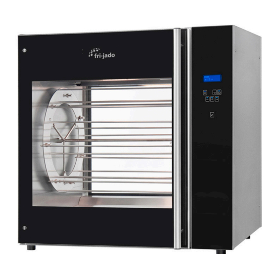
Model TDR 7 p
- NOTICE -
This manual is prepared for the use of trained Service Technicians and should
not be used by those not properly qualified. If you have attended a training
for this product, you may be qualified to perform all the procedures in this
manual.
This manual is not intended to be all encompassing. If you have not attended a
training for this product, you should read, in its entirety, the repair procedure
you wish to perform to determine if you have the necessary tools, instru-
ments and skills required to perform the procedure. Procedures for which you
do not have the necessary tools, instruments and skills should be performed
by a trained technician.
Reproduction or other use of this Manual, without the express written consent of
Fri-Jado, is prohibited.
Service Manual Turbo Deli Rotisserie
form 9120929 rev. 04/2021
II
Advertisement
Table of Contents
Troubleshooting

Subscribe to Our Youtube Channel
Related Manuals for Fri-Jado TDR 5p


Summary of Contents for Fri-Jado TDR 5p
- Page 1 SERVICE MANUAL Turbo Deli Rotisserie MODELS TDR 5m TDR 5p TDR 7 m TDR 7 p/i Model TDR 7 p - NOTICE - This manual is prepared for the use of trained Service Technicians and should not be used by those not properly qualified. If you have attended a training for this product, you may be qualified to perform all the procedures in this manual.
- Page 2 TABLE OF CONTENTS EMPTY PAGE EMPTY PAGE Service Manual Turbo Deli Rotisserie form 9120929 rev. 04/2021 Page 2 PKII...
- Page 3 TABLE OF CONTENTS Versions Version Issue date Remarks dd/mm/yy 2020 pre-release Merging of previous manuals from TDR m, TDR p and TDR i. Addition of TDRp with 9192400 pcb board 20210415 15-04-2021 First release 20210430 30-04-2021 Minor changes Service Manual Turbo Deli Rotisserie form 9120929 rev.
-
Page 4: Table Of Contents
TABLE OF CONTENTS INDEX Index ................................4 General technical data ..........................6 Technical Data ............................6 Programming instructions TDR p ......................7 Connecting mains power ........................7 Overview of control panel ........................7 Switching on ............................7 Entering the Manager or Service menu ....................8 The USB option read and store (cook books or parameters) ............ - Page 5 TDR 7/8 Parts list Sheet metal ......................69 Fasteners ............................... 70 Electrical diagrams ..........................72 Circuit diagram TDR 5P and 7p (from serial nr. 100097688) ............72 Wiring diagram TDR 5P and 7p (from serial nr. 100097688) ............73 Overview of CPU board ........................74 Overview of Power &...
-
Page 6: General Technical Data
GENERAL TECHNICAL DATA This manual covers the TDR electric oven models. All of the information, illustrations and specifications contained in this manual are based on the latest product information available at the time of printing. TECHNICAL DATA American Models TDR 5 TDR 7 TDR 5+5 TDR 7+7... -
Page 7: Programming Instructions Tdr P
PROGRAMMING INSTRUCTIONS TDR P CONNECTING MAINS POWER Messages on screen when connecting mains power. Note the bootloader version. Bootloader (Vx.xx.xx) Bootloader (Vx.xx.xx) Bootloader (Vx.xx.xx) No USB stick found Loading application Starting application In progress ...% Bootloader (Vx.xx.xx) Parameters init OK Checking CRC In progress ...% Read language files... -
Page 8: Entering The Manager Or Service Menu
PROGRAMMING INSTRUCTIONS TDR p ENTERING THE MANAGER OR SERVICE MENU Entering the manager menu Entering the service menu Chicken Chicken 98 99 1 3 4 6 6 7 98 99 1 3 4 6 6 7 5 sec. Choose figure Choose figure and confirm (4x) and confirm (4x) - Page 9 PROGRAMMING INSTRUCTIONS TDR p Options in the service menu Option Description Store cook-books and / or parameters to USB. Read cook-books and / or parameters from USB. Function Function test of inputs and outputs, including the keypad Parameters Edit manager parameters. Clock Set time / date and format time / date (12 / 24 clock) Counter...
-
Page 10: The Usb Option Read And Store (Cook Books Or Parameters)
PROGRAMMING INSTRUCTIONS TDR p THE USB OPTION READ AND STORE (COOK BOOKS OR PARAMETERS) Enter the manager or service menu as described before. Also see chapter “Files on USB drive” Manager menu Servicemenu Edit Fu.. Read Store USB read and store USB read and store Read Sto. -
Page 11: Files On The Usb Drive (Strict Rules)
PROGRAMMING INSTRUCTIONS TDR p FILES ON THE USB DRIVE (STRICT RULES) These files can be found on the USB drive regarding the TDRp. The highligted folders and files are fixed and made by the TDRp controller. The other files can be named by yourself, but PAR1.CSV there are strict rules. - Page 12 PROGRAMMING INSTRUCTIONS TDR p Preparing the software (firmware) 3. Connect the mains supply The software comes in a .zip file. The name cor- responds with the version of the software. For example: V1_05_07.zip. 1. Extract the zip file 4. The following messages appear Bootloader version V1.01.02 -USB stick found starting upgrade...
-
Page 13: Manager And Service Parameters
PROGRAMMING INSTRUCTIONS TDR p MANAGER AND SERVICE PARAMETERS Entering the manager parameters Entering the service parameters Chicken Chicken 98 99 1 3 4 6 6 7 98 99 1 3 4 6 6 7 5 sec. Choose figure Choose figure and confirm (4x) and confirm (4x) 4 8 7 8... -
Page 14: Description Of Parameters
PROGRAMMING INSTRUCTIONS TDR p DESCRIPTION OF PARAMETERS In the manager menu, only the green parameters are visible Parameter Description Preheat allowed Enables or disables a preheat step prior to the cooking program (steps) Yes > Preheat is allowed. In the cooking program you can still choose whether or not to preheat. - Page 15 PROGRAMMING INSTRUCTIONS TDR p Parameter Description Lights out Choice of lighting during opening of the door in standby position. The lights will go on for 20 seconds. key beep choice for beep or no beep, with key operation. Temp. offset Temperature offset of PT1000 sensor.
-
Page 16: The Automatic Cook Correction
PROGRAMMING INSTRUCTIONS TDR p THE AUTOMATIC COOK CORRECTION The automatic cook correction facility will automaticly add or deduct time to the pro- grammed cooking time in order to have constant cooking quality. After programming a new program, the first cooking process will be the “learning” process. It is recommended to do the first cook with a half load. -
Page 17: Default Parameters Usa
PROGRAMMING INSTRUCTIONS TDR p DEFAULT PARAMETERS USA Level 1 Level 2 Default Possibilities Information 1.05.2007 software version Manager 1111 Preheat allowed yes - no Preheat temp 50 - 250 Holding allowed yes - no Holding temp 50 - 250 Cook Correction 1 yes - no Eco function 2 yes - no... - Page 18 PROGRAMMING INSTRUCTIONS TDR p EMPTY PAGE EMPTY PAGE Service Manual Turbo Deli Rotisserie form 9120929 rev. 04/2021 Page 18 PKII...
-
Page 19: Tdr8-I Programming Instructions
TDR8-I PROGRAMMING INSTRUCTIONS MENU SETTINGS TDR-I To enter the set up of the TDR AC press the on/off key for 3 seconds. Selection buttons The main screen will show 3 options: • operate Display • program • settings Select the program by pushing the corresponding key. -
Page 20: Menu Settings Tdr -I
TDR i Programming instructions MENU SETTINGS TDR -I Settings Information The Information screen will display the following information about the rotisserie: • Device type (TDRi) • Firmware version of the CPU board (version: 6.01.27 • Last error • Firmware version of the I/O board (MFMB:v1.00) Manager The manager settings are used to change local settings like temperature, date/time or to load recipes. -
Page 21: First Settings And Diagnostic Tools Tdr-I
TDR i Programming instructions FIRST SETTINGS AND DIAGNOSTIC TOOLS TDR-I Miscellaneous service settings device type After replacing a cpu board the device type needs to be filled in. set language The next setting after replacing a board is to set langu- age to local. -
Page 22: I/O Test Tdr-I
TDR i Programming instructions I/O TEST TDR-I The I/O test function gives possibili- A - Key input test ties to: B - Read out temperature of board C - Read out inputs 1. Check the key pads. D - Controlling of outputs 2. -
Page 23: Updating Software Tdr-I
TDR i Programming instructions UPDATING SOFTWARE TDR-I Preparing the software (firmware) 3. Connect the mains supply The software comes in a .zip file. The name cor- responds with the version of the software. For example: V5_00_13.zip. After extracting 4. The following messages appear Bootloader version V1.02.02 -USB stick found 1. -
Page 24: Default Parameters Version 6.01.27 Tdr-I
TDR i Programming instructions DEFAULT PARAMETERS VERSION 6.01.27 TDR-I Level 1 Level 2 Level 3 Default Possibilities Information 6.01.27 software version Manager Change Pin code 0000 0000 - 9999 Save Recipes Load Recipes Load messages Light on - off Temperature °C °C - °F Set time... - Page 25 TDR i Programming instructions Level 1 Level 2 Level 3 Default Possibilities I/O test read the inputs and set the outputs Ignore errors no - yes save HACCP log save haccp log on usb save parameters save parameters on usb load parameters load parameters from usb Service Manual Turbo Deli Rotisserie...
-
Page 26: Service Procedures
SERVICE PROCEDURES WARNING: Disconnect the electrical power to the machine at the main circuit box. Place a tag on the circuit box indicating the circuit is being serviced. ACCESS TO SERVICE PARTS TDR-P (2020) Side view Unscrew 4 screws and open the panel from the electric compartment . -
Page 27: Access To Service Parts Stacked Units
SERVICE PROCEDURES Power and I/O board untill serial number 100097687 ACCESS TO SERVICE PARTS STACKED UNITS Acces to the blower motor, heating element and light cover has to be gained through the bottom side of the upper unit.. However, for the light cover of the TDR 5, the top rotisserie has to be removed. -
Page 28: Operating Panel (General)
SERVICE PROCEDURES OPERATING PANEL (GENERAL) 1. Remove the flatcables and ground wire from the CPU board on the backside. 2. Remove the bolt, nut and ring on the top-backside of the operating panel. 3. Pull out the panel and lift, to remove the panel. -
Page 29: Broken Buzzer
SERVICE PROCEDURES BROKEN BUZZER The buzzer on the CPU board cannot be re- 12Vdc placed, it is soldered to the board. Put the plug of the new buzzer in the socket next to the existing broken buzzer (see white arrow). Note: buzzer can dangle loosely without any problem. -
Page 30: Door Switch
SERVICE PROCEDURES DOOR SWITCH 1. Remove the operation panel and the right side panel. 2. Unscrew the 2 screws and remove the switch. 3. Disconnect the wiring. Reverse the procedure to install. Note: The contact pin of the switch must run free through the chassis. -
Page 31: Replacing A Lamp
SERVICE PROCEDURES REPLACING A LAMP Unscrew the bolts and remove the protection guard of the Halogen lamp. Do not touch the glassof the lamp with your hands! Otherwise clean with alcohol LAMP HOLDER For units from serial number 100075954. 1. Remove both side panels from the rotisse- rie. -
Page 32: Blower Motor
SERVICE PROCEDURES BLOWER MOTOR Dismounting the blower assembly. 1. Remove both side panels and the top pa- 2. Remove the blower panel 3. Remove the M5 nut and washer from the motor shaft 4. Pull the turbine from the shaft. A puller is delivered with the new blower kit. -
Page 33: Heating Element
SERVICE PROCEDURES HEATING ELEMENT Dismounting the heating element. 1. Remove both side panels and the top pa- nel. 2. Note the wiring number and write down if necessary. 3. Disconnect the wiring. Note! Hold the rear nut with an open end spanner! 4. -
Page 34: Rotor Drive Motor
SERVICE PROCEDURES ROTOR DRIVE MOTOR Dismounting the rotor motor: Note, #4 and #5 are applicable from serial number 100075954. 1. Remove the side panel at the operator- panel side. 2. Mark the position of the motor on the bracket. 3. Take the rotor shaft out of the cooking cavity. - Page 35 SERVICE PROCEDURES Centering of Mounting the rotor motor shaft in hole 1. Mount the motor on the bracket using the previous made mark (see #2 from disassembling). 2. The motor shaft should come through the center of the hole!! 3. Connect the wiring of the (new) motor. See previous page for position of wires.
-
Page 36: High Limit Thermostat
SERVICE PROCEDURES HIGH LIMIT THERMOSTAT Front side Front side Back side Back side 1. Remove the right side panel. 2. Remove the blower panel on the inside of the oven (this is only to check if the probe is on the right place). TDR 5 TDR 5 TDR 8... -
Page 37: Door Inside
SERVICE PROCEDURES DOOR INSIDE 1. Pull the inside door from the outside door. 2. Lift the inside door upward out of the hinges. 3. Place the new door in the hinges. 4. Close the inside door on the outside door. Note: Tightening of nuts max. -
Page 38: Electrical Tests
ELECTRICAL TESTS WARNING: Disconnect the electrical power to the machine at the main circuit box. Place a tag on the circuit box indicating the circuit is being serviced. MEASURING THE HEATING ELEMENTS Heating element TDR 5 ±600Ω 200-208V (USA) 230V (EUR) E3 1800W 24 Ω... - Page 39 Electrical tests Blower of rotisserie ∞ Ω Blue PH1 208/240V 50/60Hz 1,8A White 5uF 400V Thermally protected 500V Thermistor White 0 Ω Black 64 Ω 37 Ω 27 Ω The 6µF capacitor General Even with a capacitance meter it is impossible to determine for sure if the capacitor is ok or not, because it can be leaking when it is connected to mains power.
-
Page 40: Measuring The Rotor (Drive) Motor
Electrical tests MEASURING THE ROTOR (DRIVE) MOTOR White 120 Ω Brown 240 Ω 120 Ω White (A) ∞ MΩ 500V MEASURING THE 500W LAMP ±10 Ω 230V 500Watt MEASURING THE PT1000 SENSOR The oven temperature is controlled by a PT1000 sensor, mounted in the top at the side. -
Page 41: Trouble Shooting
TROUBLE SHOOTING OVERVIEW OF ERROR CODES TDR-P Error 11. 1. PT sensor malfunction.(resistance below 1000 Ω) Reading < 0°C (32°F) 2. Wiring PT sensor shortened. 3. Environment below freezing point Error 33. 1. PT sensor malfunction.(resistance higher than 2200 Ω) Reading > 315°C (600°F) 2. -
Page 42: Error 55 Explanation
TROUBLE SHOOTING ERROR 55 EXPLANATION Temp. increase °C / 2 minutes minutes Note: 1. Measuring starts 5 minutes after beginning of a heating step. 2. Duration is 5 periods of 2 minutes. 3. Measuring stops at 150°C/302°F or when temp. in cabinet is < 30°C than the set temperature. -
Page 43: Trouble Shooting By Symptom
TROUBLE SHOOTING TROUBLE SHOOTING BY SYMPTOM. Symptom Possible causes No power to oven controls. 1. Main breaker open. 2. Fuse burned (F1). 3. Fuse power and I/O board burned (F3). 4. Electronic control inoperative. 5. Wiring or flatcable loose/broken. Main fuse or breaker blows. 1. - Page 44 TROUBLE SHOOTING Symptom Possible causes Oven temperature does not 1. (safety) thermostat malfunction. reach desired temperature. 2. Contactor inoperative. P / I 3. PT 1000 sensor malfunction. 4. Sensor (probe) not in right place. 5. Thermostat malfunction P / I 6.
-
Page 45: Trouble Shooting By Part / Function
TROUBLE SHOOTING TROUBLE SHOOTING BY PART / FUNCTION. Descrip- Symptoms Possible cause Action tion of part / function Inside door Broken glass Slamming of door. Give instruction to operator. Fastening bolts and nuts Tighten all fastenings. are loose. No PTFE ring between Mount new glass with PTFE rings between steel and glass. - Page 46 TROUBLE SHOOTING Descrip- Symptoms Possible cause Action tion of part / function Drive motor Motor doesn’t Wiring. Check the wiring. Check the power to the motor. Coil malfunction. Check insulation value of coil with Megger and / or on 500V. Minimum value is 0.5 MΩ. main fuse burned Check resistance of the coils.
- Page 47 TROUBLE SHOOTING Descrip- Symptoms Possible cause Action tion of part / function M models only Main switch No power to all, Wiring. Check the wiring on the switch. or some oven Malfunction of the cams Check the cams. controls. on the switch. Switch comes in, Contacts burned.
- Page 48 TROUBLE SHOOTING Descrip- Symptoms Possible cause Action tion of part / function Keypad(s) do No possibility to One or more keys don’t Check functions of keypad(s), see not react make a program function. “function”parameter in service menu. Check flat cable connection between CPU board and keypad.
-
Page 49: Trouble Shooting The Tdw Warmer
TROUBLE SHOOTING TROUBLE SHOOTING THE TDW WARMER Symptom Possible causes No power to warmer controls. 1. Main breaker open. 2. Switch malfunction. 3. Wiring loose. Main fuse or breaker blows. 1. Wiring incorrectly. 2. Heating element or blower shorted. 3. Wiring shorted. Blower motor does not run. -
Page 50: Exploded Views And Partslists
EXPLODED VIEWS AND PARTSLISTS TDRP, ELECTRICAL PARTS 21 (TDR7/8) 20 (TDR5) TDR-p 200-208V 400V Service Manual Turbo Deli Rotisserie form 9120929 rev. 04/2021 Page 50 PKII... -
Page 51: Tdrp, Parts List Electrical Parts
EXPLODED VIEWS AND PARTSLISTS TDRP, PARTS LIST ELECTRICAL PARTS Part number Description Part number Description 9290344s Electric panel, ass. 9298522 Panel, customer side, ass. + keypad, TDR5 9292040s CPU board + LCD 9298523 Control panel, ass. + 2 keypads, 9292041 Keypad + short flatcable TDR5 9192400s... -
Page 52: Tdr-P/I Connectors And Wiring
EXPLODED VIEWS AND PARTSLISTS TDR-P/I CONNECTORS AND WIRING 1050 mm (41 1/4”) 450 mm (17 3/4”) <--2 <--1 <--3 <--2 <--1 <--2 <--3 <--4 <--5 <--6 <--2 <--3 <--4 <--6 Service Manual Turbo Deli Rotisserie form 9120929 rev. 04/2021 Page 52 PKII... -
Page 53: Tdr-P/I Parts List Connectors And Wiring
EXPLODED VIEWS AND PARTSLISTS TDR-P/I PARTS LIST CONNECTORS AND WIRING Part number Description Part number Description 9293021 Conversion cable 3 to 5-pole 9290858 Wire repair set TDRp J2 9290859 Wire repair set TDRp J6 9310850s Wire repair set inputs 9310816s Connection set TDR hood 9291176 Crimp contact, inputs... -
Page 54: Tdr-P/I, Electrical Parts Untill Serial Number 100097687
EXPLODED VIEWS AND PARTSLISTS TDR-P/I, ELECTRICAL PARTS UNTILL SERIAL NUMBER 100097687 21 (TDR7/8) 20 (TDR5) TDR-p TDR-i Service Manual Turbo Deli Rotisserie form 9120929 rev. 04/2021 Page 54 PKII... -
Page 55: Tdr-P/I, Parts List Electrical Parts Untill Serial Number 100097687
EXPLODED VIEWS AND PARTSLISTS TDR-P/I, PARTS LIST ELECTRICAL PARTS UNTILL SERIAL NUMBER 100097687 Part number Description Part number Description 9292040s CPU board + LCD 9298520 Control panel, ass. + keypad, TDR5 9292041 Keypad + short flatcable 9298524 Panel, left side, TDR5 9172314 Ribbon cable L= 1500 mm, 14 pins 9298522... -
Page 56: Tdrm, Electrical Parts
EXPLODED VIEWS AND PARTSLISTS TDRM, ELECTRICAL PARTS 21 (TDR7/8) 20 (TDR5) Service Manual Turbo Deli Rotisserie form 9120929 rev. 04/2021 Page 56 PKII... -
Page 57: Tdrm, Parts List Electrical Parts
EXPLODED VIEWS AND PARTSLISTS TDRM, PARTS LIST ELECTRICAL PARTS Part number Description Part number Description 9293001s Gearmotor, complete with drive head, 9171140 Main switch TDR5 8033659 Connecting block 9293002s Gearmotor, complete with drive head, 9294064 Bracket temperature sensors TDR7/8 9294063 Bracket temperature sensors 3701233s Door switch... -
Page 58: Tdr Doors
EXPLODED VIEWS AND PARTSLISTS TDR DOORS Service Manual Turbo Deli Rotisserie form 9120929 rev. 04/2021 Page 58 PKII... -
Page 59: Tdr Parts List Doors
EXPLODED VIEWS AND PARTSLISTS TDR PARTS LIST DOORS Part number Description Part number Description TDR 5 9298500s Door service side, ass., TDR5m 9298503s Door customer side, ass., TDR5m 9298502s Door inside, ass., TDR5m TDR 7/8 9298510s Door service side, ass., TDR7/8m 9298513s Door customer side, ass., TDR7/8m 9298512s... -
Page 60: Tdr Illumination
EXPLODED VIEWS AND PARTSLISTS TDR ILLUMINATION Untill serial number 100075953 From serial number 100075954 Service Manual Turbo Deli Rotisserie form 9120929 rev. 04/2021 Page 60 PKII... -
Page 61: Tdr Parts List Illumination
EXPLODED VIEWS AND PARTSLISTS TDR PARTS LIST ILLUMINATION Part number Description Part number Description 9291001s Infrared Halogen lamp 500W 9052826 Lamp holder 9291122 Connector, 2 pole 2300121 Terminal block, ceramic 9294463s Light fixture + end plate L and R 9292061 Protection guard, infrared lamp 9294227 Channel, lamp wiring... -
Page 62: Tdr 5 Rotor
EXPLODED VIEWS AND PARTSLISTS TDR 5 ROTOR TDR 5 TDR 7/8 ROTOR Untill serial number 100075953 Untill serial number 100089663 9292295 Service Manual Turbo Deli Rotisserie form 9120929 rev. 04/2021 Page 62 PKII... -
Page 63: Tdr 5 Parts List Rotor
EXPLODED VIEWS AND PARTSLISTS TDR 5 PARTS LIST ROTOR Part number Description Part number Description 9293001s Gearmotor, complete with drive head, TDR5 9293002s Gearmotor, complete with drive head, TDR7/8 3701228 Capacitor 2.5 uF 9146951 Ass. Rotor TDR5 9170571 Rotor shaft 9174369 Rotor disc 3 mm 9172062... -
Page 64: Tdr 5 Heating
EXPLODED VIEWS AND PARTSLISTS TDR 5 HEATING TDR 7/8 HEATING Service Manual Turbo Deli Rotisserie form 9120929 rev. 04/2021 Page 64 PKII... -
Page 65: Tdr 5/7/8 Parts List Heating
EXPLODED VIEWS AND PARTSLISTS TDR 5/7/8 PARTS LIST HEATING Part number Description Part number Description 9292029s Heating element 208 V, 5.4 KW, ass. 9292028s Heating element 208 V, 9.3 KW 9298550s Blower, ass. TDR5 9298551s Blower, ass. TDR7/8 9192034 Capacitor 6 uF 9293020s Blower motor, with conversion cable 3 to 5 pole... -
Page 66: Tdr 5 Sheet Metal
EXPLODED VIEWS AND PARTSLISTS TDR 5 SHEET METAL Service Manual Turbo Deli Rotisserie form 9120929 rev. 04/2021 Page 66 PKII... -
Page 67: Tdr 5 Parts List Sheet Metal
EXPLODED VIEWS AND PARTSLISTS TDR 5 PARTS LIST SHEET METAL Part number Description Part number Description 9174154 Adjusting bracket 9171015 Grommet, plastic 9290444 Support plate, rotor motor 4288232 Screw M5x12, SS cross recess, wide button head 9171125 Leg, rubber 50 mm 9172053 Nut M5, for sheet metal 9294353... -
Page 68: Tdr 7/8 Sheet Metal
EXPLODED VIEWS AND PARTSLISTS TDR 7/8 SHEET METAL >sr. nr. 100075953 41/2015 TDR8 Service Manual Turbo Deli Rotisserie form 9120929 rev. 04/2021 Page 68 PKII... -
Page 69: Tdr 7/8 Parts List Sheet Metal
EXPLODED VIEWS AND PARTSLISTS TDR 7/8 PARTS LIST SHEET METAL Part number Description Part number Description 9174154 Adjusting bracket 9290444 Support plate, rotor motor 9171125 Leg, rubber 50 mm 9294366 Grease guard. 9171008 Drain-tap with handle 9261022 Strain relief M25 9261023 Nut, strain relief M25 9172066... -
Page 70: Fasteners
EXPLODED VIEWS AND PARTSLISTS FASTENERS Pos Part nr Pos Part nr Description Description 4280107 Bolt M6x20 ZP 3701248 Spacer 7mm, Ø3,2x6 NP 4289559 Lockwasher M6, serrated ZP 0149296 Spacer 10mm, Ø4,2x8 Nylon 4288321 Screw M5x16, SS socket button head. 9057347 Spacer 10mm, Ø5,2x10 Nylon 4285092 Nut M6, black serrated 0141165 Screw M5x25, SS Cross recess pan head... - Page 71 EXPLODED VIEWS AND PARTSLISTS Pos Part nr Description 4287557 Washer M10 9073149 Wingnut M6, SS 2800082 Wingnut M6, Brass Nickle plated 4312027 Connection nut M5x15, ZP 4280540 Screw M5x6, SS countersunk 4311215 Screw , socket head M6 x 30 0141123 Screw pan head, Philips M5x10, SS 149299 Spacer, Ø8xø4,2, H15, black...
-
Page 72: Electrical Diagrams
ELECTRICAL DIAGRAMS CIRCUIT DIAGRAM TDR 5P AND 7P (FROM SERIAL NR. 100097688) Service Manual Turbo Deli Rotisserie form 9120929 rev. 04/2021 Page 72 PKII... -
Page 73: Wiring Diagram Tdr 5P And 7P (From Serial Nr. 100097688)
ELECTRICAL DIAGRAMS WIRING DIAGRAM TDR 5P AND 7P (FROM SERIAL NR. 100097688) Hi limit THERMOSTAT MAX 320°C Heating Elements 17 18 J8-2 white 44 54 J8-1 PT-1000 J9-2 J9-1 J10-2 J10-1 12 13 10 11 J13-2 J13-1 DOOR SWITCH 33 26 53... -
Page 74: Overview Of Cpu Board
ELECTRICAL DIAGRAMS OVERVIEW OF CPU BOARD Socket for spare buzzer (in case the one on board is broken) ON / OFF UNDO Socket for 14p ribbon LIST cable, from Power&I/O board USB socket FORWARD Socket for second key panel BACK Key panel ROTOR Ribbon cable connection between CPU board and Power&... -
Page 75: Overview Of Power & I/O Board (From Serial Nr. 100097688)
ELECTRICAL DIAGRAMS OVERVIEW OF POWER & I/O BOARD (FROM SERIAL NR. 100097688) All relays, and the digital inputs J13 - J17 have LED’s , showing the contact is closed or which relay is active. Connectors and relays in red are always functional and in blue are optional. 205-204 lter position 26-53 Thermistor in Blower Signal... -
Page 76: Circuit Diagram Tdr 5P And 7P (Untill Serial Nr. 100097687)
ELECTRICAL DIAGRAMS CIRCUIT DIAGRAM TDR 5P AND 7P (UNTILL SERIAL NR. 100097687) Service Manual Turbo Deli Rotisserie form 9120929 rev. 04/2021 Page 76 PKII... -
Page 77: Wiring Diagram Tdr 5P And 7P (Untill Serial Nr. 100097687)
ELECTRICAL DIAGRAMS WIRING DIAGRAM TDR 5P AND 7P (UNTILL SERIAL NR. 100097687) Service Manual Turbo Deli Rotisserie form 9120929 rev. 04/2021 Page 77... -
Page 78: Circuit Diagram Tdr 5M And 7M
ELECTRICAL DIAGRAMS CIRCUIT DIAGRAM TDR 5M AND 7M Service Manual Turbo Deli Rotisserie form 9120929 rev. 04/2021 Page 78 PKII... -
Page 79: Wiring Diagram Tdr 5M And 7M
ELECTRICAL DIAGRAMS WIRING DIAGRAM TDR 5M AND 7M Service Manual Turbo Deli Rotisserie form 9120929 rev. 04/2021 Page 79... -
Page 80: Circuit Diagram Tdw 5
ELECTRICAL DIAGRAMS CIRCUIT DIAGRAM TDW 5 9290850 CIRCUIT DIAGRAM TDW 7 Service Manual Turbo Deli Rotisserie form 9120929 rev. 04/2021 Page 80 PKII... -
Page 81: Wiring Diagram Tdw 5
ELECTRICAL DIAGRAMS WIRING DIAGRAM TDW 5 9290860 WIRING DIAGRAM TDW 7 9290861 Service Manual Turbo Deli Rotisserie form 9120929 rev. 04/2021 Page 81... -
Page 82: Electrical Diagrams (Before September 2014)
ELECTRICAL DIAGRAMS (BEFORE SEPTEMBER 2014) CIRCUIT DIAGRAM TDR 5P AND 7P (UNTILL SERIAL NUMBER 100069000) Service Manual Turbo Deli Rotisserie form 9120929 rev. 04/2021 Page 82 PKII... -
Page 83: Wiring Diagram Tdr 5P And 7P (Untill Serial Number 100069000)
ELECTRICAL DIAGRAMS WIRING DIAGRAM TDR 5P AND 7P (UNTILL SERIAL NUMBER 100069000) Service Manual Turbo Deli Rotisserie form 9120929 rev. 04/2021 Page 83... -
Page 84: Circuit Diagram Tdr 5P And 7P (Untill Serial Number 100059841)
ELECTRICAL DIAGRAMS CIRCUIT DIAGRAM TDR 5P AND 7P (UNTILL SERIAL NUMBER 100059841) Service Manual Turbo Deli Rotisserie form 9120929 rev. 04/2021 Page 84 PKII... -
Page 85: Wiring Diagram Tdr 5P And 7P (Untill Serial Number 100059841)
ELECTRICAL DIAGRAMS WIRING DIAGRAM TDR 5P AND 7P (UNTILL SERIAL NUMBER 100059841) Service Manual Turbo Deli Rotisserie form 9120929 rev. 04/2021 Page 85... -
Page 86: Circuit Diagram Tdr 5P And 7P (Untill Serial Number 100058736)
ELECTRICAL DIAGRAMS CIRCUIT DIAGRAM TDR 5P AND 7P (UNTILL SERIAL NUMBER 100058736) Service Manual Turbo Deli Rotisserie form 9120929 rev. 04/2021 Page 86 PKII... -
Page 87: Wiring Diagram Tdr 5P And 7P (Untill Serial Number 100058736)
ELECTRICAL DIAGRAMS WIRING DIAGRAM TDR 5P AND 7P (UNTILL SERIAL NUMBER 100058736) Service Manual Turbo Deli Rotisserie form 9120929 rev. 04/2021 Page 87... -
Page 88: Circuit Diagram Tdr 5M And 7M (Untill Serial Number 100059841)
ELECTRICAL DIAGRAMS CIRCUIT DIAGRAM TDR 5M AND 7M (UNTILL SERIAL NUMBER 100059841) Service Manual Turbo Deli Rotisserie form 9120929 rev. 04/2021 Page 88 PKII... -
Page 89: Wiring Diagram Tdr 5M And 7M (Untill Serial Number 100059841)
ELECTRICAL DIAGRAMS WIRING DIAGRAM TDR 5M AND 7M (UNTILL SERIAL NUMBER 100059841) Service Manual Turbo Deli Rotisserie form 9120929 rev. 04/2021 Page 89... -
Page 90: Circuit Diagram Tdr 5M And 7M (Untill Serial Number 100058736)
ELECTRICAL DIAGRAMS CIRCUIT DIAGRAM TDR 5M AND 7M (UNTILL SERIAL NUMBER 100058736) Service Manual Turbo Deli Rotisserie form 9120929 rev. 04/2021 Page 90 PKII... -
Page 91: Wiring Diagram Tdr 5M And 7M (Untill Serial Number 100058736)
ELECTRICAL DIAGRAMS WIRING DIAGRAM TDR 5M AND 7M (UNTILL SERIAL NUMBER 100058736) Service Manual Turbo Deli Rotisserie form 9120929 rev. 04/2021 Page 91... - Page 92 For technical support call: +1 877 374 5236 Fri-Jado Inc. • 1401 Davey Road • Suite 100 • Woodridge IL 60517 • USA • fax +1 630 689 1424 • us.info@frijado.com • www.frijado.com • USA • toll free 877-FRI-JADO...
Need help?
Do you have a question about the TDR 5p and is the answer not in the manual?
Questions and answers