Fri-Jado TDR 5 P eco Service Manual
Hide thumbs
Also See for TDR 5 P eco:
- Installation manual (32 pages) ,
- Installation manual (28 pages) ,
- Service manual (100 pages)
Table of Contents
Advertisement
SERVICE MANUAL
TDR P
eco
TDW - WARMER MODELS
MODELS
TDR 5 P
eco
TDR 8 P
eco
TDW 5 P
TDW 8 P
WWW.FRIJADO.COM
- ROTISSERIE OVEN MODELS
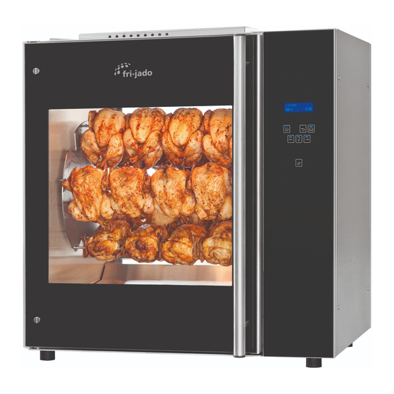
Model TDR 5 P
This manual is prepared for the use of trained Service Technicians
and should not be used by those not properly qualified. If you
have attended a training for this product, you may be qualified to
perform all the procedures in this manual.
This manual is not intended to be all encompassing. If you have
not attended a training for this product, you should read, in its
entirety, the repair procedure you wish to perform to determine
if you have the necessary tools, instruments and skills required to
perform the procedure. Procedures for which you do not have the
necessary tools, instruments and skills should be performed by a
Reproduction or other use of this Manual, without the express
written consent of Fri-Jado, is prohibited.
eco
- NOTICE -
trained technician.
Service Manual TDR5/8 P TDW5/8 P form 9123911 rev. 10/2014
Model TDR 8 P
eco
Advertisement
Table of Contents
Troubleshooting

Related Manuals for Fri-Jado TDR 5 P eco


Summary of Contents for Fri-Jado TDR 5 P eco
- Page 1 Procedures for which you do not have the necessary tools, instruments and skills should be performed by a trained technician. Reproduction or other use of this Manual, without the express written consent of Fri-Jado, is prohibited. WWW.FRIJADO.COM Service Manual TDR5/8 P TDW5/8 P form 9123911 rev. 10/2014...
- Page 2 Page 2 Service Manual TDR5/8 P TDW5/8 P form 9123911 rev. 10/2014...
- Page 3 TABLE OF CONTENTS Versions Version Issue date Remarks dd/mm/yy 07/2012 01/07/2012 First release. 02/2013 01/02/2013 TDW 5 and 8 added. Small adjustments. 05/2013 01/05/2013 TDR 5 and TDW 5 deeper version added as standard. Small adjust- ments. 09/2013 30/09/2013 Sizes for TDR 5 adapted in Technical data 01/2014 01/01/2014 Small textual changes.
-
Page 4: Table Of Contents
TABLE OF CONTENTS INDEX Index ................................4 General technical data ..........................6 Technical data ............................6 Programming instructions for the TDR 5 - 8 P and TDW 5 - 8 ............... 7 The automatic cook correction ......................25 Removal and replacement of parts for the TDR 5 and TDR 8 .............. 26 Right or left side panel ........................ - Page 5 TABLE OF CONTENTS Parameter List P ........................... 51 Electrical tests and service procedures ....................52 Heating element test ........................... 52 Contactor, drive motor and blower test ..................... 52 PT1000 sensor test ..........................53 Error codes on display ......................... 53 Control location ........................... 54 General troubleshooting list ........................
-
Page 6: General Technical Data
GENERAL TECHNICAL DATA GENERAL TECHNICAL DATA This manual covers the TDR P series rotisserie ovens and the TDW series warmers. Ovens and warming cabinets come in two sizes. Ovens and cabinets will alsobe delivered in stacked versions. • TDR 5 – Oven with five spits ( 15 to 20 chickens ) •... -
Page 7: Programming Instructions For The Tdr 5 - 8 P And Tdw 5 - 8
PROGRAMMING INSTRUCTIONS PROGRAMMING INSTRUCTIONS FOR THE TDR 5 - 8 P AND TDW 5 - 8 OPERATING PANEL CHICKEN Display 85 1 Undo List On / Off Back Forward Rotor Function OPERATING PANEL WARMER On / Off Switching the unit On / Off Undo Go back to previous menu List... - Page 8 TDR-P Models OPERATION Buttons are lit when functional. 5.1. Operation of the rotisserie 1. Press Start. 2. Display shows Fri-Jado logo. 3. Display shows software version. Interface P Eco Version x.x.x 4. Display shows latest cooking Drumstick program. 5. Use the arrow buttons for program selection.
- Page 9 PROGRAMMING INSTRUCTIONS TDR-P Models 9. Pre-heat ready LOAD (unit returns a sound signal). Note: press OK or open the door to START stop the signal. Display shows the next step of the program. Note: Screen 9 and 11 alternate each 5 seconds. 10.
-
Page 10: Service Manual Tdr5/8 P Tdw5/8 P Form 9123911 Rev
PROGRAMMING INSTRUCTIONS TDR-P Models 18. A reminder to measure the core Measure Core Temp. temperature appears. Note: Screen 17 and 18 alternate every 5 seconds. 2 Chicken 19. (Optional, visible for 5 min.) request for additional time (minutes) after Add time? opening the door. - Page 11 PROGRAMMING INSTRUCTIONS OPERATION OPTIONS TDR-P Models 5.2. Operation options 5.2.1. To end a running program. 1. Press and hold start for 3 seconds. Stop? 2. Make a choice with the arrow buttons. Note: Select NO to abort ending the program. 3.
- Page 12 PROGRAMMING INSTRUCTIONS TDR-P Models 5.2.3. Check the remaining time in a program 1 Chicken 1. Use the arrow buttons to show the remaining time pro step. 230°C P123 0:05 1 Chicken 2. Time left at step 1 (first digit blinks). 230°C P123 0:01 3.
- Page 13 PROGRAMMING INSTRUCTIONS TDR-P Models 6. Press the OK button to update the screen (automatically refreshed every 15 seconds). 7. Press List button to go back. 1 Chicken 8. Display returns to the original operating display. 180°C P123 0:20 5.2.5. Eco function Optional: only available when activated 1 Chicken in the service menu.
- Page 14 PROGRAMMING INSTRUCTIONS TDR-P Models 5.2.7. Display information 180°C 1. Display shows the programmed 0:20 temperature and time. 2. Press the list button. 1 Chicken 3. Display shows after 3 seconds cooking step + temperature + time. 180°C P123 0:20 Note: the current cooking step is underlined.
- Page 15 PROGRAMMING INSTRUCTIONS TDR-P Models PROGRAMMING MANAGER MENU 6.1. Manager menu items Programming Parameters Change pin Pre-Heat Clock Edit Preheat temperature Transfer Delete Holding Version Copy Holding temperature Cook correction* Reading recipes Eco function* Store recipes Language Big digits Sound preheat Sound step Sound done * Only visible when selected in the service menu.
- Page 16 PROGRAMMING INSTRUCTIONS TDR-P Models Pin 0 - - - 6. Enter the User PIN code. Give User PIN code Note: the original PIN code is 1111. The operator can change the User PIN code. 7. Use the arrow button to enter the PIN code.
- Page 17 PROGRAMMING INSTRUCTIONS TDR-P Models 15. The first available number is shown. Choose new number Note: use the arrow right button to select the next available number. 16. Press the OK button to confirm. 10 A-------------- 17. Enter the recipe name. for others Use the arrow button to change the character.
- Page 18 PROGRAMMING INSTRUCTIONS TDR-P Models 22. Press the OK button to confirm. 23. Set the “step 1” temperature. 10 Step 1 Starting with the first digit. Temp 1 - - °C 24. Use the arrow buttons to increase/decrease the value of the selected digit.
- Page 19 PROGRAMMING INSTRUCTIONS TDR-P Models 32. Press the OK button to confirm. 33. Set the second digit. 10 Step 1 Temp 215 °C Time 21 - 34. Press the OK button to confirm. 35. Set the last digit. 10 Step 1 Temp 215 °C Time 210 36.
- Page 20 PROGRAMMING INSTRUCTIONS TDR-P Models 40. When ready programming press the OK button to confirm. 41. Save the finished programs. 10 TEST Save 1Disc Note: if the program is not saved all changes are lost! 42. Press the OK button to confirm. 43.
- Page 21 PROGRAMMING INSTRUCTIONS TDR-P Models MANAGER MENU: PARAMETERS 6.3. Programming parameters 1. Press the list button. Pin * * * * 2. Enter your user PIN code. Give User PIN code 3. Press the OK button to confirm. 4. Press the arrow buttons to select MANAGER MENU Parameters.
- Page 22 PROGRAMMING INSTRUCTIONS TDR-P Models 9. Use the arrow buttons to select Language: English Change, Next or Previous. Change Next 1Previous Press back to enter the manager menu. 10. Use the arrow buttons to select Save and press the OK button to confirm. This is valid for software version V1.04-09 or higher.
- Page 23 PROGRAMMING INSTRUCTIONS TDR-P Models MANAGER MENU: CHANGE PINCODE 6.4. Change pin code 1. Manager menu. MANAGER MENU 2. Select Change Pin. Para Change Pin 1Clock 3. Press the OK button. 4. Enter the new pin code. Pin 0 0 0 0 5.
- Page 24 PROGRAMMING INSTRUCTIONS OPTIONS MANAGER MENU: USB TDR-P Models 6.8. 1. Manager menu. MANAGER MENU USB Programming 1Para. 2. Use the arrow buttons to select the USB function. 3. Screen shows the USB function. MANAGER MENU Place the USB stick into the USB- Edit slot.
-
Page 25: The Automatic Cook Correction
PROGRAMMING INSTRUCTIONS THE AUTOMATIC COOK CORRECTION The automatic cook correction facility will automaticly add or deduct time to the pro grammed cooking time in order to have constant cooking quality. After programming a new program, the first cooking process will be the “learning” process. It is recommended to do the first cook with a half load. -
Page 26: Removal And Replacement Of Parts For The Tdr 5 And Tdr 8
REMOVAL AND REPLACEMENT OF PARTS REMOVAL AND REPLACEMENT OF PARTS FOR THE TDR 5 AND TDR 8 WARNING: Disconnect the electrical power to the machine at the main circuit box. Place a tag on the circuit box indica- ting the circuit is being serviced. RIGHT OR LEFT SIDE PANEL 1. -
Page 27: Electric Panel
REMOVAL AND REPLACEMENT OF PARTS ELECTRIC PANEL 1. Remove the right side panel according prior procedure. 2. Disconnect the wiring. 3. Remove on the inside bottom of the elec- tric panel the bolt and nuts. 4. Slide the electric panel upwards to remove this. -
Page 28: Power And I/O Board
REMOVAL AND REPLACEMENT OF PARTS POWER AND I/O BOARD 1. Remove the right side panel according prior procedure. 2. Disconnect the wiring and flatcable on the board. 3. Remove the board from the clips by pres- sing the clips together. 4. -
Page 29: Replacing Of Broken Buzzer
REMOVAL AND REPLACEMENT OF PARTS REPLACING OF BROKEN BUZZER 1. Remove the right side panel according prior procedure. 2. Remove the operating panel according prior procedure. 3. Stick connector of new buzzer in plug next to the existing broken buzzer (see white arrow). -
Page 30: Infra-Red Halogen Lamp Holder
REMOVAL AND REPLACEMENT OF PARTS INFRA-RED HALOGEN LAMP HOLDER Caution: Do not touch the glass with your hands. The moisture from your hands could affect the live span of the lamp. This moi- sture can be removed with alcohol while the lamp is cold. -
Page 31: Infra-Red Halogen Lamp Holder Bottom Rotisserie (Stacked Tdr 8)
REMOVAL AND REPLACEMENT OF PARTS INFRA-RED HALOGEN LAMP HOLDER BOTTOM ROTISSERIE (STACKED TDR 8) Warning: When changing the lamp holder for the TDR 5, the top rotisserie has to be remo- ved. Caution: Do not touch the glass with your hands. -
Page 32: Contactor
REMOVAL AND REPLACEMENT OF PARTS CONTACTOR 1. Remove the right side panel according prior procedure. 2. Disconnect the lead wires to the contactor. 3. Push on the locking tab down with a screw driver and lift out to remove it from the mounting bracket. -
Page 33: High Limit Thermostat
REMOVAL AND REPLACEMENT OF PARTS HIGH LIMIT THERMOSTAT 1. Remove the right side panel according prior procedure. 2. Remove the fan plate on the ceiling on the inside of the oven (this is only to check TDR 5 TDR 8 if the probe is on the right place). -
Page 34: Blower Motor
REMOVAL AND REPLACEMENT OF PARTS BLOWER MOTOR 1. Remove the right side panel and the top cover according to prior procedures. 2. Remove the rotor discs and the fan plate on the ceiling inside the oven. 3. Remove the nut and washer on the fan blade and remove the fan blade with the help of the puller. -
Page 35: Blower Motor Bottom Rotisserie (Stacked Tdr)
REMOVAL AND REPLACEMENT OF PARTS BLOWER MOTOR BOTTOM ROTISSERIE (STACKED TDR) 1. Remove the right side panel according prior procedures. 2. Remove the rotor discs and the fan plate on the ceiling inside the oven in the bottom oven. 3. Remove the nut and washer on the fan blade and remove the fan blade with the help of the puller. -
Page 36: Drive Motor
REMOVAL AND REPLACEMENT OF PARTS DRIVE MOTOR 1. Remove the right side panel and rotor discs according prior procedure. 2. Disconnect the wiring of the motor. Check where the wire, marked A is connected. 3. Remove the screws that secure the fan co- ver and remove the cover. -
Page 37: Heating Element
REMOVAL AND REPLACEMENT OF PARTS HEATING ELEMENT 1. Remove the right side panel, the top cover and the fan plate according prior procedures. 2. Remove the nut(s) on the inside top that fastens the element to the top side. 3. Disconnect the wiring from the element. 4. -
Page 38: Door Glass Inside
REMOVAL AND REPLACEMENT OF PARTS DOOR GLASS INSIDE 1. Lift the inside door upward out of the hinges and place it on a table. 2. Remove the nuts and rings on the pro- files of the door. 3. Remove the profiles from the glass. 4. -
Page 39: Removal And Replacement Of Parts For The Tdw 5 And Tdw 8
REMOVAL AND REPLACEMENT OF PARTS REMOVAL AND REPLACEMENT OF PARTS FOR THE TDW 5 AND TDW 8 WARNING: Disconnect the electrical power to the machine at the main circuit box. Place a tag on the circuit box indica- ting the circuit is being serviced. BLOWER MOTOR 1. -
Page 40: Thermostat
REMOVAL AND REPLACEMENT OF PARTS THERMOSTAT 1. Remove the right side panel and the fan plate according prior procedures. 2. Remove the thermostat probe from the clamp inside the cavity (see arrow) and guide it outside through the opening. 3. Disconnect the wiring from the ther- mostat. -
Page 41: Heating Element
REMOVAL AND REPLACEMENT OF PARTS HEATING ELEMENT 1. Remove the right side panel, racks, bottom plate and the fan plate according prior procedures. 2. Disconnect the wiring from the element. 3. Remove the nuts and rings that secure the element and remove the element. 4. -
Page 42: Parameter Listing Tdr P
The service section is only accesible for qualified service technicians. The start up screen lists general information such as software version number, model name and Fri-Jado company logo. Please make sure you read the paragraph titled “adapting parameters” before changing parameters. - Page 43 PARAMETERS OPTIONS MANAGER MENU To enter the manager menu press and hold the List key. The manager section can be protect- ed by a seperate password. The standard number is “1111”, This password can be changed inside the manager menu. Manager Menu PROGRAMMING PARAMETERS...
-
Page 44: Manager Menu - Description Of The Submenus
PARAMETERS MANAGER MENU - DESCRIPTION OF THE SUBMENUS Menu section: Manager menu Parameter Description In this menu you can read recipies from the USB stick to the CPU board, or store programs from the CPU to the USB stick. Programming In this menu you can process the cooking programs. -
Page 45: Service Menu - Description Of The Submenus
PARAMETERS SERVICE MENU - DESCRIPTION OF THE SUBMENUS Menu section: Service menu Parameter Description In this menu you can read recIpies from the USB stick to the CPU board. And you can store recipies, parameters and LOG data to the USB stick. Function This menu allows access to the I/O test screen, Through this, several inputs and outputs of the machine can be monitored and toggled. - Page 46 PARAMETERS Parameter list Service menu Parameter Description Ecocook allowed This parameter alows the ecocook to be activated or not. Ecocook on yes means that the accumulated heat in the cavity will be used to cook the product and to save energy. Heat- ing elements will not be activated during the last period of the last grilling step.
-
Page 47: Adapting Parameters
Only in case the unit has older software!! This software, supplied by Fri-Jado comes in a “zip” file with the version number of the software, for example “V1_4_09.zip”. The file needs to be copied on a USB stick. (disk “USB drive (F:)”... -
Page 48: Read And Store Recipies In Manager Menu
PARAMETERS READ AND STORE RECIPIES IN MANAGER MENU Recipes can be read and stored from both the Manager menu and the Service menu. Recipes can only be read to, or stored from the CPU board by means of a memory stick. The transfer is always done out of a folder called “Programs”. -
Page 49: Read And Store Recipies And Parameters In Service Menu
PARAMETERS READ AND STORE RECIPIES AND PARAMETERS IN SERVICE MENU Recipes can be read and stored from both the Manager menu and the Service menu. Recipes can only be read to, or stored from the CPU board by means of a memory stick. The transfer is always done out of a folder called “programs”. - Page 50 PARAMETERS Parameters can only be read to, or stored from the CPU board by means of a memory stick. The transfer is always done out of a folder called “PARAMS”. This folder has to be placed direct on the memory stick and cannot be placed in another folder, otherwise it will not work.
-
Page 51: Parameter List P
PARAMETERS PARAMETER LIST P If set to “0” then the error 55 function is not active. Has to be set on “no”until serial number 100067527. Service Manual TDR5/8 P TDW5/8 P form 9123911 rev. 10/2014 Page 51... -
Page 52: Electrical Tests And Service Procedures
ELECTRICAL TESTS AND SERVICE PROCEDURES ELECTRICAL TESTS AND SERVICE PROCEDURES WARNING: Disconnect the electrical power to the machine at the main circuit box. Place a tag on the circuit box indica- ting the circuit is being serviced. HEATING ELEMENT TEST Note: When testing the resistance of the element remove the wiring. -
Page 53: Pt1000 Sensor Test
ELECTRICAL TESTS AND SERVICE PROCEDURES PT1000 SENSOR TEST Note: When testing the resistance of the sen- Temperature Resistance Ω sor remove the wiring. Refer to the removal °F °C ± 5 Ohms and replacement part of the manual on how 1000 1062 to do this. -
Page 54: Control Location
ELECTRICAL TESTS AND SERVICE PROCEDURES CONTROL LOCATION CHICKEN Display 85 1 2 3 7 Undo List On / Off Back Forward Rotor 0 = Off 1 = 25°C / 77°F 2 = 40°C / 104°F Function 3 = 60°C / 140°F On / Off Switching the unit On / Off 4 = 80°C / 176°F... -
Page 55: General Troubleshooting List
TROUBLESHOOTING GENERAL TROUBLESHOOTING LIST TROUBLESHOOTING FOR THE TDR 5 AND 8 ROTISSERIES Symptom Possible causes No power to oven controls. 1. Main breaker open. 2. Fuse burned (F1). 3. Fuse power and I/O board burned (F3). 4. Electronic control inoperative. 5. - Page 56 TROUBLESHOOTING Symptom Possible causes All beep functions do not function 1. Obsolete software (older than V1.03.06). Load latest sofware. anymore. If no software is available unplug the unit for 5 seconds and plug in again. Now the beep signal will work again for 49 days. 2.
-
Page 57: Troubleshooting For The Tdw 5 And 8 Warmers
TROUBLESHOOTING TROUBLESHOOTING FOR THE TDW 5 AND 8 WARMERS Symptom Possible causes No power to warmer controls. 1. Main breaker open. 2. Switch malfunction. 3. Wiring loose. Main fuse or breaker blows. 1. Wiring incorrectly. 2. Heating element or blower shorted. 3. -
Page 58: Error 55 Explanation
TROUBLESHOOTING ERROR 55 EXPLANATION Temp. increase °C / 2 minutes minutes Note: 1. Measuring starts 5 minutes after beginning of a heating step. 2. Duration is 5 periods of 2 minutes. 3. Measuring stops at 150°C/302°F or when temp. in cabinet is < 30°C than the set temperature. Necessary line currents: TDR8 with neutral 3x 16A. -
Page 59: Analytic Troubleshooting List
TROUBLESHOOTING ANALYTIC TROUBLESHOOTING LIST SERVICING AND REPAIRING THE TDR 5 AND 8 ROTISSERIES This is an analytic description for servicing and repairing all major parts of the rotisseries and warmers. It consists off 4 basic steps to recognize and solve the problems. These steps are: Symptoms. - Page 60 TROUBLESHOOTING Description of part Symptoms Possible causes Solving: checking/action Thermostat Contactor doesn’t come in Wiring. Check the wiring. after starting of program Thermostat malfunc- Check if the thermostat is making tion. contact. Contactor switches off be- Thermostat malfunc- Check if the thermostat is turned fore reaching the adjusted tion.
- Page 61 TROUBLESHOOTING Description of part Symptoms Possible causes Solving: checking/action Capacitor Drive motor or blower Wiring. Check the wiring. don’t work Capacitor malfunc- Check function after connecting a tion. new capacitor. Checking of capacitor: Discharge capacitor with screwdri- ver. Set meter on MΩ and connect the pins of the meter on contacts, value runs up.
- Page 62 TROUBLESHOOTING Description of part Symptoms Possible causes Solving: checking/action Display/CPU on No illumination on display Wiring. Check the wiring. operation panel and power I/O board Check the power on the CPU board by the 2 flashing red LED’s just near the flatcable on the power and I/O board.
- Page 63 TROUBLESHOOTING Description of part Symptoms Possible causes Solving: checking/action Drive motor Motor doesn’t run Wiring. Check the wiring. Check the power to the motor. Coil malfunction. Check resistance of the coils. See also table on page 52. Between whiteA and white wire 234Ω.
-
Page 64: Servicing And Repairing The Tdw 5 And 8 P Warmers
TROUBLESHOOTING SERVICING AND REPAIRING THE TDW 5 AND 8 P WARMERS Description of part Symptoms Possible causes Solving: checking/action Outside door Broken glass. Slamming of door. Give instruction to operator. Fastening bolts Tighten all fastenings. and nuts are loose. No PTFE ring Mount new glass with PTFE rings bet- between steel and ween glass and steel. - Page 65 TROUBLESHOOTING Description of part Symptoms Possible causes Solving: checking/action Capacitor Drive motor or blower Wiring. Check the wiring. doesn’t work. Capacitor malfunc- Check function after connecting a new tion. capacitor. Checking of capacitor: Discharge capacitor with screwdriver. Set meter on MΩ and connect the pins of the meter on contacts, value runs up.
-
Page 66: Exploded Views & Partlists
EXPLODED VIEWS AND PARTLISTS EXPLODED VIEWS & PARTLISTS TDR 5 P - SHEET METAL WORK D-0158-01 Page 66 Service Manual TDR5/8 P TDW5/8 P form 9123911 rev. 10/2014... - Page 67 EXPLODED VIEWS AND PARTLISTS Item Part number Qty. Description ..Frame, ass. 9171125 Leg, rubber 50 mm 9294353 Side panel, left 9294126 Side panel, left (till serial nr. 100061480) 9294352 Side panel, right 9294125 Side panel, right (till serial nr. 100061480) 9294160 Top cover 9294350...
-
Page 68: Tdr 5 P - Components
EXPLODED VIEWS AND PARTLISTS TDR 5 P - COMPONENTS 48-12 48-1 48-8 48-13 48-3 48-4 48-7 48-2 48-9 48-5 48-6 48-10 49-1 40-1 40-2 70-5 40-3 73-1 70-6 70-5 70-7 70-8 70-4 70-9 70-10 70-11 70-13 70-12 70-17 70-15 70-2 70-16 70-3 70-1... - Page 69 EXPLODED VIEWS AND PARTLISTS Item Part number Qty. Description Item Part number Qty. Description 9146951 Rotorset ass., stainless steel 9291010 Cover USB adapte 40-1 9170571 Rotor shaft 4285010 Nut M3 40-2 9174369 Rotor disc 3 mm 0141050 Screw M3x10 40-3 0142975 Socket head screw M6 x 20 SS 9290210...
-
Page 70: Tdr 5 P - Doors
EXPLODED VIEWS AND PARTLISTS TDR 5 P - DOORS 91-1 91-2 91-5 92-11 92-2 92-6 91-4 92-4 91-6 91-3 92-5 90-5 90-7 91-12 90-4 90-8 91-7 91-8 90-17 90-2 91.C 92-1 92-11 92-3 91-12 90-1 90-6 91-1 91-13 91-7 90-3 91-8 91-2 91-9... - Page 71 EXPLODED VIEWS AND PARTLISTS Item Part number Qty. Description Item Part number Qty. Description 90.S 9298500S Door service side, ass. 9298502S Door inside, ass. 90-1 4280558 Screw M5 x 16 SS 92-1 9292011 Glass, inside door 90-2 3702342 Flange bush, PTFE 3 mm 92-2 9290457 Hinge profile...
-
Page 72: Tdr 8 P - Sheet Metal Work
EXPLODED VIEWS AND PARTLISTS TDR 8 P - SHEET METAL WORK D-0159-01 TDR8 Page 72 Service Manual TDR5/8 P TDW5/8 P form 9123911 rev. 10/2014... - Page 73 EXPLODED VIEWS AND PARTLISTS Item Part number Qty. Description ..Frame, ass. 9171125 Leg, rubber 50 mm 9294180 Side panel, left 9294018 Side panel, right 9294009 Top cover 9294032 Top plate 9294045 Cover, removeable 9290401 Mounting plate, blower 9290405 Drawer 9171008 Drain-tap with handle 9294014...
-
Page 74: Tdr 8 P - Components
EXPLODED VIEWS AND PARTLISTS TDR 8 P - COMPONENTS 48-1 48-12 48-8 48-3 48-13 48-4 48-7 48-9 48-2 48-5 48-10 48-6 49-1 40-1 40-2 40-3 40-4 40-2 70-5 40-5 40-6 73-1 70-6 70-5 70-7 70-8 70-4 70-9 70-10 70-11 70-13 70-12 70-17 70-15... - Page 75 EXPLODED VIEWS AND PARTLISTS Item Part number Qty. Description Item Part number Qty. Description 9172274 Rotorset ass., stainless steel 9044140 Sensor cable 40-1 9070272 Rotor shaft 9291011 USB adapter 40-2 9174623 Rotor disc 3 mm 9291012 USB cable 40-3 4288231 Tensilock bolt M5 x 10 9291010 Cover USB adapte...
-
Page 76: Tdr 8 P - Doors
EXPLODED VIEWS AND PARTLISTS TDR 8 P - DOORS 91-1 91-2 91-5 92-2 92-11 92-6 92-4 91-4 91-6 92-5 91-3 90-5 91-12 90-7 91-7 92-1 90-8 90-4 91-8 90-2 90-17 91.C 92-11 91-10 91-12 92-3 91-1 90-1 90-6 91-13 91-7 91-2 90-3 91-8... - Page 77 EXPLODED VIEWS AND PARTLISTS Item Part number Qty. Description Item Part number Qty. Description 9298512S Door inside, ass. 90.S 9298510S Door service side, ass. 90-1 4280558 Screw M5 x 16 SS 92-1 9292013 Glass, inside door 90-2 3702342 Flange bush, PTFE 3 mm 92-2 9290406 Hinge profile...
-
Page 78: Tdw 5 P - Sheet Metal Work
EXPLODED VIEWS AND PARTLISTS TDW 5 P - SHEET METAL WORK TDW 5 M D-0177-01 Page 78 Service Manual TDR5/8 P TDW5/8 P form 9123911 rev. 10/2014... - Page 79 EXPLODED VIEWS AND PARTLISTS Item Part number Qty. Description ..Frame, ass. 9294353 Side panel, left 9294126 Side panel, left (till serial nr. 100061480) 9294352 Side panel, right 9294125 Side panel, right (till serial nr. 100061480) 9290492 Reinforcement plate, left 9290510 Reinforcement plate, left (till serial nr.
-
Page 80: Tdw 5 P - Components
EXPLODED VIEWS AND PARTLISTS TDW 5 P - COMPONENTS 46-1 46-5 46-2 45-5 46-4 46-3 45-6 45-7 45-4 46-6 46-C 45-16 45-2 46-11 46-1 45-1 46-7 46-6 46-2 45-3 46-7 46-8 60-5 60-4 60-3 60-2 60-1 46-10 50-1 45.S 46-9 59-1 50-2 45-10... - Page 81 EXPLODED VIEWS AND PARTLISTS Item Part number Qty. Description Item Part number Qty. Description 9294271 Lamp shade 9110048 Blower 9052826 Lamp holder 50-1 9110153 Fan blade 9082774 Lamp. Halotherm 200 W 50-2 9073150 Wing nut, left hand threaded 2300121 Terminal block, Ceramic 9040722 Connecting block 9292061...
-
Page 82: Tdw 8 P - Sheet Metal Work
EXPLODED VIEWS AND PARTLISTS TDW 8 P - SHEET METAL WORK TDW 7 M D-0178-01 Page 82 Service Manual TDR5/8 P TDW5/8 P form 9123911 rev. 10/2014... - Page 83 EXPLODED VIEWS AND PARTLISTS Item Part number Qty. Description ..Frame, ass. 9294031 Side panel, left 9294018 Side panel, right 9290500 Reinforcement plate, left 9290501 Reinforcement plate, right 9294110 Reinforcement, left top 9294258 Reinforcement, right top 9294045 Cover, removable 9294263 Top plate 9290502 Ceiling...
-
Page 84: Tdw 8 P - Components
EXPLODED VIEWS AND PARTLISTS TDW 8 P - COMPONENTS 46-1 46-5 46-2 45-5 46-4 46-3 45-6 45-7 45-4 45-16 45-2 46-6 46-7 45-1 46-C 45-3 46-11 46-1 46-6 46-7 46-2 60-5 46-8 60-4 60-3 60-2 60-1 45.S 59-1 50-1 46-10 46-9 50-2 45-10... - Page 85 EXPLODED VIEWS AND PARTLISTS Item Part number Qty. Description Item Part number Qty. Description 9294271 Lamp shade 9110048 Blower 9052826 Lamp holder 50-1 9110153 Fan blade 9082774 Lamp. Halotherm 200 W 50-2 9073150 Wing nut, left hand threaded 2300121 Terminal block, Ceramic 9040722 Connecting block 9292061...
-
Page 86: Electrical Diagrams
ELECTRICAL DIAGRAMS ELECTRICAL DIAGRAMS CIRCUIT DIAGRAM TDR 5 AND 8 P Page 86 Service Manual TDR5/8 P TDW5/8 P form 9123911 rev. 10/2014... -
Page 87: Wiring Diagram Tdr 5 And 8 P
ELECTRICAL DIAGRAMS WIRING DIAGRAM TDR 5 AND 8 P Service Manual TDR5/8 P TDW5/8 P form 9123911 rev. 10/2014 Page 87... -
Page 88: Circuit Diagram Tdr 5 And 8 P (Untill Serial Number 100067527)
ELECTRICAL DIAGRAMS CIRCUIT DIAGRAM TDR 5 AND 8 P (UNTILL SERIAL NUMBER 100067527) Page 88 Service Manual TDR5/8 P TDW5/8 P form 9123911 rev. 10/2014... -
Page 89: Wiring Diagram Tdr 5 And 8 P (Until Serial Number 100067527)
ELECTRICAL DIAGRAMS WIRING DIAGRAM TDR 5 AND 8 P (UNTIL SERIAL NUMBER 100067527) Service Manual TDR5/8 P TDW5/8 P form 9123911 rev. 10/2014 Page 89... -
Page 90: Circuit Diagram Tdr 5 P (Until 01-07-2012)
ELECTRICAL DIAGRAMS CIRCUIT DIAGRAM TDR 5 P (UNTIL 01-07-2012) Page 90 Service Manual TDR5/8 P TDW5/8 P form 9123911 rev. 10/2014... -
Page 91: Circuit Diagram Tdr 8 P (Until 01-07-2012)
ELECTRICAL DIAGRAMS CIRCUIT DIAGRAM TDR 8 P (UNTIL 01-07-2012) Service Manual TDR5/8 P TDW5/8 P form 9123911 rev. 10/2014 Page 91... -
Page 92: Wiring Diagram Tdr 5 And 8 P (Until 01-07-2012)
ELECTRICAL DIAGRAMS WIRING DIAGRAM TDR 5 AND 8 P (UNTIL 01-07-2012) Page 92 Service Manual TDR5/8 P TDW5/8 P form 9123911 rev. 10/2014... -
Page 93: Circuit Diagram Tdr 5 + 5 P Bottom Unit (Until 01-07-2013)
ELECTRICAL DIAGRAMS CIRCUIT DIAGRAM TDR 5 + 5 P BOTTOM UNIT (UNTIL 01-07-2013) Service Manual TDR5/8 P TDW5/8 P form 9123911 rev. 10/2014 Page 93... -
Page 94: Circuit Diagram Tdr 8 + 8 P Bottom Unit (Until 01-07-2012)
ELECTRICAL DIAGRAMS CIRCUIT DIAGRAM TDR 8 + 8 P BOTTOM UNIT (UNTIL 01-07-2012) Page 94 Service Manual TDR5/8 P TDW5/8 P form 9123911 rev. 10/2014... -
Page 95: Wiring Diagram Tdr 5 + 5 And 8 + 8 P Bottom Unit (Until 01-07-2012)
ELECTRICAL DIAGRAMS WIRING DIAGRAM TDR 5 + 5 AND 8 + 8 P BOTTOM UNIT (UNTIL 01-07-2012) Service Manual TDR5/8 P TDW5/8 P form 9123911 rev. 10/2014 Page 95... -
Page 96: Circuit Diagram Tdr 5 P With Tdw 5 (Until 01-07-2012)
ELECTRICAL DIAGRAMS CIRCUIT DIAGRAM TDR 5 P WITH TDW 5 (UNTIL 01-07-2012) Page 96 Service Manual TDR5/8 P TDW5/8 P form 9123911 rev. 10/2014... -
Page 97: Wiring Diagram Tdr 5 P With Tdw 5 (Until 01-07-2012)
ELECTRICAL DIAGRAMS WIRING DIAGRAM TDR 5 P WITH TDW 5 (UNTIL 01-07-2012) Service Manual TDR5/8 P TDW5/8 P form 9123911 rev. 10/2014 Page 97... -
Page 98: Circuit Diagram Tdw 5
ELECTRICAL DIAGRAMS CIRCUIT DIAGRAM TDW 5 Page 98 Service Manual TDR5/8 P TDW5/8 P form 9123911 rev. 10/2014... -
Page 99: Wiring Diagram Tdw 5
ELECTRICAL DIAGRAMS WIRING DIAGRAM TDW 5 Service Manual TDR5/8 P TDW5/8 P form 9123911 rev. 10/2014 Page 99... -
Page 100: Circuit Diagram Tdw 8
ELECTRICAL DIAGRAMS CIRCUIT DIAGRAM TDW 8 Page 100 Service Manual TDR5/8 P TDW5/8 P form 9123911 rev. 10/2014... -
Page 101: Wiring Diagram Tdw 8
ELECTRICAL DIAGRAMS WIRING DIAGRAM TDW 8 Service Manual TDR5/8 P TDW5/8 P form 9123911 rev. 10/2014 Page 101... - Page 102 Page 102 Service Manual TDR5/8 P TDW5/8 P form 9123911 rev. 10/2014...
- Page 103 Service Manual TDR5/8 P TDW5/8 P form 9123911 rev. 10/2014 Page 103...
- Page 104 Fri-Jado B.V. • P.O. Box 560 • 4870 AN • Etten-Leur • The Netherlands • tel +31 76 50 85 400 • fax +31 76 50 85 444 • info@frijado.com • www.frijado.com...
Need help?
Do you have a question about the TDR 5 P eco and is the answer not in the manual?
Questions and answers