
Related Manuals for Manitou M26-2 D ST5 S1 EU


Summary of Contents for Manitou M26-2 D ST5 S1 EU
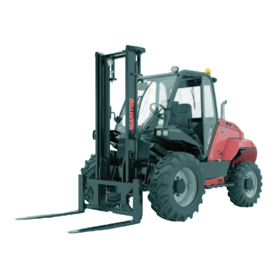
- Page 1 647835 EN-USM3 (D-03/2023) M26-2 D ST5 S1 EU M26-4 D ST5 S1 EU M30-2 D ST5 S1 EU M30-4 D ST5 S1 EU M40-2 D ST5 S1 EU M40-4 D ST5 S1 EU M50-2 D ST5 S1 EU M50-4 D ST5 S1 EU...
- Page 2 - Descriptions and figures are nonbinding. - MANITOU reserves the right to change its models and their equipment without being required to update this manual. - The MANITOU network, consisting exclusively of qualified professionals, is available to answer all your questions.
- Page 3 1 st EDITION A-02/2021 B-02/2022 UPDATE C-08/2022 2-1 – 2-52 3-43 – 3-44 D-03/2023 1-1 – 1-20 2-4 – 2-10 ; 2-14 – 2-29 ; 2-34 ; 2-36 – 2-62 3-4 – 3-5 ; 3-9 ; 3-11 ; 3-14 – 3-17 ; 3-38 – 3-41...
- Page 4 Manitou Group. In the event that Manitou Group authorizes a Manitou Group machine user to access all or part of this database, Manitou Group, as producer of this database, cedes to the user only a right to personal, non-exclusive, non transferable use of the database, and only by access to an information technology platform hosted by a server owned or controlled by Manitou Group.
- Page 5 1 - OPERATING AND SAFETY INSTRUCTIONS 2 - DESCRIPTION 3 - MAINTENANCE 4 - ATTACHMENTS...
- Page 7 1 - OPERATING AND SAFETY INSTRUCTIONS 1 - 1...
-
Page 8: Table Of Contents
1 - OPERATING AND SAFETY INSTRUCTIONS INSTRUCTIONS TO THE COMPANY MANAGER THE SITE THE OPERATOR THE MACHINE A - SUITABILITY OF THE MACHINE FOR THE TASK ........... . . 1-4 B - ADAPTING THE MACHINE TO USUAL ENVIRONMENTAL CONDITIONS . - Page 9 PROLONGED MACHINE SHUTDOWN 1-16 INTRODUCTION 1-16 PREPARATION OF THE MACHINE 1-16 DEF (Diesel Exhaust Fluid) TANK 1-16 PROTECTING THE ENGINE 1-16 MACHINE PROTECTION 1-16 RETURNING THE MACHINE TO SERVICE 1-17 DISPOSING OF THE MACHINE 1-18 RECYCLING OF MATERIALS 1-18 METALS ................1-18 PLASTICS .
-
Page 10: Instructions To The Company Manager
- This machine is a lift truck designed for handling (moving, storing or transporting) a load. - MANITOU has ensured that this machine is suitable for use under the standard operating conditions defined in this operator's manual, with a STATIC TEST COEFFICIENT OF 1.33 and a DYNAMIC TEST COEFFICIENT OF 1, as specified in harmonized standard ISO 3691-1 for masted forklift trucks. -
Page 11: C - Modifying The Machine
- Our machines comply with Directive 2004/108/EC concerning electromagnetic compatibility (EMC) (UK: Electromagnetic Compatibility Regulations 2016), and with the corresponding harmonized standard EN 12895. Their correct operation is no longer guaranteed if they are used within areas in which the electromagnetic fields exceed the limit specified by this standard (10 V/m). -
Page 12: Instructions To The Operator
Failure to respect the safety and operating instructions, or the instructions for repairing or servicing your machine, may lead to serious, even fatal accidents. In order to reduce or prevent any danger with a MANITOU-approved attachment, follow the instructions in paragraph: 4 - ADAPTABLE ATTACHMENTS AVAILABLE ON THE RANGE: INTRODUCTION. -
Page 13: Operating Instructions Unladen And Laden
OPERATING INSTRUCTIONS UNLADEN AND LADEN A - BEFORE STARTING UP THE MACHINE - Perform the daily maintenance operations ( 3 - MAINTENANCE). - Make sure that the driver's cab is clean, particularly the floor and floor mat. Check that no movable objects may hinder operation of the machine. -
Page 14: D - Visibility
- Never stack loads on uneven ground, they may tip over. - The load or the attachment must not be left just above a structure for long periods at a time because of the descending mast. In such a case, a constant watch must be kept and the height of the forks or the attachment readjusted if necessary. - In the case of work near to overhead lines, ensure that the safety distance is sufficient between the machine's working area and the overhead line. -
Page 15: F - Operating The Machine
F - OPERATING THE MACHINE SAFETY INSTRUCTIONS IMPORTANT We would like to draw the operators' attention to the risks involved in using the machine, in particular: - Risk of losing control. - Risk of loss of lateral and frontal stability of the machine. The operator must remain in control of the machine. -
Page 16: G - Stopping The Machine
G - STOPPING THE MACHINE SAFETY INSTRUCTIONS - Never leave the ignition key in the machine during the operator's absence. - When the machine is stationary, or if the operator has to leave his cab (even for a moment), place the forks or attachment on the ground, apply the parking brake and place the forward/reverse selector in neutral. -
Page 17: Instructions For Handling A Load
INSTRUCTIONS FOR HANDLING A LOAD A - CHOICE OF ATTACHMENTS - Only attachments approved by MANITOU can be used on its machines. - Make sure the attachment is appropriate for the work to be done ( 4 - ADAPTABLE ATTACHMENTS AVAILABLE ON THE RANGE). -
Page 18: D - Picking Up A Load On The Ground
D - PICKING UP A LOAD ON THE GROUND - Advance the machine perpendicular to the load, with the forks in a horizontal position (Fig. D1). - Adjust the fork spread and centring in connection with the load (fig. D2) (optional solutions exist, consult your dealer). - Page 19 - Lift the load slightly (1) and tilt the carriage (2) backward to stabilize the load (Fig. E3). - Tilt the load sufficiently backwards to ensure its stability. - Reverse the machine (1) very carefully and gently to free the load. Lower the mast (2) to bring the load into transport position (fig. E4).
-
Page 20: Machine Maintenance Instructions
MACHINE MAINTENANCE INSTRUCTIONS GENERAL INSTRUCTIONS - Make sure the area is adequately ventilated before starting up the machine. - Wear clothes suitable for the maintenance of the machine. Avoid wearing jewelry and loose clothes. Tie back and protect your hair, if necessary. - Before doing any work on the machine: •... -
Page 21: Welding
WELDING - Disconnect the battery before any welding operations on the machine. - When carrying out electric welding work on the machine, connect the negative cable from the equipment directly to the part being welded so as to avoid very high current passing through the alternator. - Never carry out welding or work which gives off heat on an assembled tire. - Page 22 PROLONGED MACHINE SHUTDOWN INTRODUCTION The following recommendations are intended to prevent the machine from being damaged when it is withdrawn from service for an extended period. IMPORTANT Procedures to follow if the machine is not to be used for a long time and for starting it up again afterwards must be performed by your dealership. This period of long-term stoppage must not exceed 12 months.
- Page 23 RETURNING THE MACHINE TO SERVICE - Remove the waterproof adhesive tape from all the orifices. - Refit and reconnect the battery. - Remove the protection from the cylinder rods. - Perform the daily maintenance operations ( 3 - MAINTENANCE). - Put the handbrake on and remove the axle stands. - Drain and clean the fuel tank ( 3 - MAINTENANCE).
- Page 24 • Glass items can be removed and collected for processing by glaziers. ENVIRONMENTAL PROTECTION By entrusting the maintenance of your machine to the MANITOU network, the risk of pollution is limited and the contribution to environmental protection is made. WORN OR DAMAGED PARTS •...
- Page 25 2 - DESCRIPTION 2 - 1...
- Page 26 2 - 2...
- Page 27 2 - DESCRIPTION SAFETY PLATES AND STICKERS IDENTIFICATION OF THE LIFT TRUCK SPECIFICATIONS 2-10 M26-2 … / M26-4 … SPECIFICATIONS 2-12 M30-2 … / M30-4 … SPECIFICATIONS 2-14 M40-2 … / M40-4 … SPECIFICATIONS 2-16 M50-2 … / M50-4 … MAST CHARACTERISTICS AND LOAD CHARTS 2-18 M26-2 …...
-
Page 28: Safety Plates And Stickers
SAFETY PLATES AND STICKERS IMPORTANT Clean all stickers and safety plates so that they are legible. Any safety plates and stickers which are illegible or damaged must be replaced. Check that stickers and safety plates are present after replacing any spare parts. EXTERNAL PLATES AND STICKERS REF. - Page 29 STICKERS AND PLATES IN THE CAB REF. REFERENCE DESCRIPTION 300681 - Safety instruction 234806 - Differential lock instruction M26-2 … / M30-2 … / M40-2 … / M50-2 … 234806 - Differential lock instruction (OPTION) M26-4 … / M30-4 … 239594 - Sound power level 104 dB 33460...
- Page 30 REF. REFERENCE DESCRIPTION 52588137 - CAN ICES-2 NMB-2 52618158 - Prop 65 warning 52618159 - Prop 65 exhaust warning 52700667 - Warning "roll away" 52700692 - Caution "no riders" 2 - 6...
- Page 31 STICKERS AND PLATES UNDER THE ENGINE HOOD REF. REFERENCE DESCRIPTION 293887 - Anti-freeze 259398 - Water / diesel separator 716906 - Fan hazard 52778005 - Extreme cold instruction (Option) 52806826 - Fuses and relays N°293887 – 35°C – 31°F FUEL / WATER SEPARATOR FUEL 259398...
-
Page 32: Identification Of The Lift Truck
“Max vertical force (on trailer hook)” Effort vertical maximum (sur crochet de remorque) “Drag strain” Effort de traction ENGINE “MODEL” Model “SER.NO” Numéro de série “CODE” Code fournisseur “SPEC” Spécification “CSPEC” Code spécification GEARBOX MANITOU reference Type Serial number FRONT AXLE Type Serial number MANITOU reference 2 - 8... - Page 33 REAR AXLE M26-4 … / M30-4 … / M40-4 … / M50-4 … Type Serial number MANITOU reference OVERHEAD GUARD CAB (OPTION) “Constructeur” Manufacturer “Type Cabine” Cab Type “N° de série” Serial number ROLLER MASTS MANITOU reference CHASSIS Serial number / Product Identification Number ATTACHMENT MANUFACTURER'S PLATE “MODELE”...
-
Page 34: Specifications
M26-2 … / M26-4 … N.B.: The specifications given are not binding on the manufacturer and may be modified without notice. -Manufacturer MANITOU -Model type M26-2 D ST5 S1 EU M26-4 D ST5 S1 EU -Propulsion: battery, diesel, gasoline, LPG, mains Diesel Diesel... - Page 35 -Engine manufacturer/Type DEUTZ TCD 2.9 DEUTZ TCD 2.9 -Engine power rating (ISO 1585) -Rated speed 2300 2300 7.3.1 -Maximum speed 3200 3200 -Number of cylinders / Displacement cm³ 4 / 2925 4 / 2925 -Fuel consumption (according to VDI cycle) emissions kg/h 13.3 17.2 -Speed control Electrical Electrical...
-
Page 36: Specifications
SPECIFICATIONS M30-2 … / M30-4 … N.B.: The specifications given are not binding on the manufacturer and may be modified without notice. -Manufacturer MANITOU -Model type M30-2 D ST5 S1 EU M30-4 D ST5 S1 EU -Propulsion: battery, diesel, gasoline, LPG, mains... - Page 37 -Engine manufacturer/Type DEUTZ TCD 2.9 DEUTZ TCD 2.9 -Engine power rating (ISO 1585) -Rated speed 2300 2300 7.3.1 -Maximum speed 3200 3200 -Number of cylinders / Displacement cm³ 4 / 2925 4 / 2925 -Fuel consumption (according to VDI cycle) emissions kg/h 13.3 17.2 -Speed control Electrical Electrical...
-
Page 38: Specifications
SPECIFICATIONS M40-2 … / M40-4 … N.B.: The specifications given are not binding on the manufacturer and may be modified without notice. -Manufacturer MANITOU -Model type M40-2 D ST5 S1 EU M40-4 D ST5 S1 EU -Propulsion: battery, diesel, gasoline, LPG, mains... - Page 39 -Engine manufacturer/Type DEUTZ TCD 2.9 DEUTZ TCD 2.9 -Engine power rating (ISO 1585) -Rated speed 2300 2300 7.3.1 -Maximum speed 3200 3200 -Number of cylinders / Displacement cm³ 4 / 2925 4 / 2925 -Fuel consumption (according to VDI cycle) emissions kg/h 14.3 18.0 -Speed control Electrical Electrical...
-
Page 40: Specifications
SPECIFICATIONS M50-2 … / M50-4 … N.B.: The specifications given are not binding on the manufacturer and may be modified without notice. -Manufacturer MANITOU -Model type M50-2 D ST5 S1 EU M50-4 D ST5 S1 EU -Propulsion: battery, diesel, gasoline, LPG, mains... - Page 41 -Engine manufacturer/Type DEUTZ TCD 2.9 DEUTZ TCD 2.9 -Engine power rating (ISO 1585) -Rated speed 2300 2300 7.3.1 -Maximum speed 3200 3200 -Number of cylinders / Displacement cm³ 4 / 2925 4 / 2925 -Fuel consumption (according to VDI cycle) ℓ/h emissions kg/h 19.5 20.8 -Speed control Electrical...
-
Page 42: Mast Characteristics And Load Charts M26-2
MAST CHARACTERISTICS AND LOAD CHARTS M26-2 … / M26-4 … TILTING LIFT HEIGHT FREE LIFT HEIGHT OF MAST STANDARD M26-2 ... MAST h3 (mm) h2 (mm) h1 (mm) h4 (mm) α (°) β (°) 3M70 3700 2696 4626 DUPLEX COMPLETE VISIBILITY 4M50 4500 3136... - Page 43 VALUES ON FORKS VALUES WITH INTEGRAL SIDE-SHIFT CARRIAGE Capacity at max. height Capacity at max. height Height at max. capacity (mm) Height at max. capacity (mm) D = 500 mm (kg) D = 500 mm (kg) 3700 2600 3700 2600 4500 2600 4500 2600 VALUES ON FORKS VALUES WITH INTEGRAL SIDE-SHIFT CARRIAGE Capacity at max.
-
Page 44: Mast Characteristics And Load Charts M30-2
MAST CHARACTERISTICS AND LOAD CHARTS M30-2 … / M30-4 … TILTING LIFT HEIGHT FREE LIFT HEIGHT OF MAST STANDARD M30-2 ... MAST h3 (mm) h2 (mm) h1 (mm) h4 (mm) α (°) β (°) 3M70 3700 2696 4626 DUPLEX COMPLETE VISIBILITY 4M50 4500 3136... - Page 45 VALUES ON FORKS VALUES WITH INTEGRAL SIDE-SHIFT CARRIAGE Capacity at max. height Capacity at max. height Height at max. capacity (mm) Height at max. capacity (mm) D = 500 mm (kg) D = 500 mm (kg) 3700 3000 3700 3000 4500 3000 4100 2600 4300 1600 4000...
-
Page 46: Mast Characteristics And Load Charts M40-2
MAST CHARACTERISTICS AND LOAD CHARTS M40-2 … / M40-4 … TILTING LIFT HEIGHT FREE LIFT HEIGHT OF MAST STANDARD M40-2 ... MAST h3 (mm) h2 (mm) h1 (mm) h4 (mm) α (°) β (°) 3M00 3000 2475 4025 3M30 3300 2625 4325 3M50 3500... - Page 47 VALUES ON FORKS VALUES WITH INTEGRAL SIDE-SHIFT CARRIAGE Capacity at max. height Capacity at max. height Height at max. capacity (mm) Height at max. capacity (mm) D = 500 mm (kg) D = 500 mm (kg) 3000 4000 3000 4000 3300 4000 3300 4000 3500 4000 3500...
-
Page 48: Mast Characteristics And Load Charts M50-2
MAST CHARACTERISTICS AND LOAD CHARTS M50-2 … / M50-4 … TILTING LIFT HEIGHT FREE LIFT HEIGHT OF MAST STANDARD M50-2 ... MAST h3 (mm) h2 (mm) h1 (mm) h4 (mm) α (°) β (°) 3M00 3000 2475 4025 3M30 3300 2625 4325 3M50 3500... - Page 49 VALUES ON FORKS VALUES WITH INTEGRAL SIDE-SHIFT CARRIAGE Capacity at max. height Capacity at max. height Height at max. capacity (mm) Height at max. capacity (mm) D = 600 mm (kg) D = 600 mm (kg) 3000 5000 3000 4700 3300 5000 3300 4700 3500 5000 3500...
- Page 50 TIRES M26-2 … / M30-2 … LOAD PER TIRE (kg) PRESSURE M26-2 D ST5 S1 EU (bar) FRONT UNLADEN FRONT (LADEN) REAR (UNLADEN) REAR (LADEN) ALLIANCE 405/70-20 14PR 149B A-323 1250 3450 15.5/80-24 AS 504 16PR TL 1250 3450 CONTINENTAL 14.5R20 18PR 143G/J MPT80 TL...
-
Page 51: Tires
TIRES M26-4 … / M30-4 … LOAD PER TIRE (kg) PRESSURE M26-4 D ST5 S1 EU (bar) FRONT UNLADEN FRONT (LADEN) REAR (UNLADEN) REAR (LADEN) ALLIANCE 405/70-20 14PR 149B A-323 1100 3300 15.5/80-24 AS 504 16PR TL 1100 3300 MICHELIN 380/75 R20 148A8 148B XMCL TL 1100 3300 ALLIANCE... -
Page 52: Tires
TIRES M40-2 … / M50-2 … LOAD PER TIRE (kg) PRESSURE M40-2 D ST5 S1 EU (bar) FRONT UNLADEN FRONT (LADEN) REAR (UNLADEN) REAR (LADEN) ALLIANCE 18-19.5 224 18PR 7,25 1300 4550 MICHELIN 18R19-5 XF TL 1300 4550 18/22.5 STABILIZER 16PR TL 1300 4550 GOODYEAR... - Page 53 TIRES M40-4 … / M50-4 … LOAD PER TIRE (kg) PRESSURE M40-4 D ST5 S1 EU (bar) FRONT UNLADEN FRONT (LADEN) REAR (UNLADEN) REAR (LADEN) MICHELIN 18R22-5 XF TL 1300 4500 MITAS 480/65-22.5 IND 16PR/163A8 MPT-06 TL 1300 4500 18/22.5 STABILIZER 16PR TL 1300 4500 15.5/80-24 AS 504 16PR TL...
- Page 54 INSTRUMENTS AND CONTROLS N.B.: All the terms such as: RIGHT, LEFT, FRONT, REAR are as seen by an observer occupying the driver's seat and looking straight ahead. 1 - DRIVER'S CAB ACCESS ..................... . . 2-32 2 - DRIVER'S SEAT .
- Page 55 2 - 31...
-
Page 56: Driver's Cab Access
1 - DRIVER'S CAB ACCESS - Face the driver's cab access to get in and out, and always use the three support points provided for this purpose. 1 - Left handle. 2 - Driver's cab pillar. 3 - Step. 2 - DRIVER'S SEAT DRIVER’S SEAT, SKAI UPHOLSTERY (STANDARD) first version DRIVER'S SEAT, FABRIC UPHOLSTERY (OPTION) -
Page 57: Seat Belt
DRIVER'S PNEUMATIC SEAT (OPTION) DESIGNED FOR MAXIMUM COMFORT, THIS SEAT CAN BE ADJUSTED AS FOLLOWS. SEAT WEIGHT AND HEIGHT ADJUSTMENT Adjust the weight when the driver is sitting on the seat. - Switch on lift truck ignition. - Move the weight adjustment lever 1 upwards to increase the weight or downwards to reduce it. -
Page 58: External Emergency Stop (Option)
5 - EXTERNAL EMERGENCY STOP (OPTION) first version IMPORTANT Be ready for hydraulic movements suddenly stopping when you press this button. If possible stop the lift truck before using the emergency stop button. - OFF (locked): Press the button to stop the engine. - ON (unlocked): Pull the button or turn it clockwise a quarter turn and release it. -
Page 59: Dashboard Handset
8 - DASHBOARD HANDSET INDICATOR LIGHTS IMPORTANT A permanently lit or flashing warning light, with the engine running, is the sign of an operating fault. The lighting of some lamps may be accompanied by an audible signal. Do not ignore this warning, consult your dealer without delay. -
Page 60: Switches
ENGINE OIL PRESSURE WARNING INDICATOR LAMP If the indicator lamp comes on when the forklift truck is running, stop the engine immediately and determine the cause ( oil level in engine crankcase). N.B.: After starting the engine, the indicator lamp remains on for a few seconds then goes out when the correct engine oil pressure is reached. - Page 61 B - FUEL LEVEL If the indicator light and the buzzer come on when the lift truck is running, you have reached the reserve fuel level and your operating time is limited. N.B.: The intermittent flashing of all the LEDs, the indicator light and the buzzer indicates a malfunction. Consult your dealer. C - REV COUNTER IMPORTANT Do not exceed the engine’s maximum speed ( SPECIFICATIONS [7.3.1]).
- Page 62 9 - SWITCHES The location of the switches may vary depending on the options. REAR AXLE CLUTCH M26-4 … / M30-4 … / M40-4 … / M50-4 … • 0 - 2 Driving wheels. • II - 4 Driving wheels (indicator lamp on). TRANSMISSION CUT-OFF •...
-
Page 63: Lighting, Horn And Turn Signals (Depending On Model)
10 - LIGHTING, HORN AND TURN SIGNALS (Depending on model) The road lights can be used without the ignition key. • A - Road lights off • B - Front and rear sidelights • C - Low beam headlights • D - High beam headlights • E - Headlight flashing (pulse) •... -
Page 64: Fuses And Relays In The Cab
11 - FUSES AND RELAYS IN THE CAB - Remove access panel 1. - Replace a blown fuse with a new fuse of the same quality and rating. - Never use a repaired fuse. FIRST VERSION MINIFUSE F1 15 A Front worklights (Option) F2 15 A Rear worklights (Option) F3 10 A Rear axle clutch. - Page 65 second version SECOND VERSION MINIFUSE F1 15 A Front worklights (Option) F2 15 A Rear worklights (Option) F3 10 A Rear axle clutch. M26-4 … / M30-4 … / M40-4 … / M50-4 … F4 7.5 A Rotating beacon light (Option) F5 7.5 A Car radio (Option) 3 A “EasyMANAGER”...
-
Page 66: Fuses And Relays Under The Engine Hood
12 - FUSES AND RELAYS UNDER THE ENGINE HOOD - Remove access panel 1. - Remove the cover 2. - Replace a blown fuse with a new fuse of the same quality and rating. - Never use a repaired fuse. FIRST VERSION first version MINIFUSE 5A Engine diagnostics plug... -
Page 67: Accelerator Pedal
14 - ACCELERATOR PEDAL 15 - SERVICE BRAKE PEDAL AND TRANSMISSION CUT-OFF The pedal acts on the front wheels by means of a hydraulic brake system enabling the lift truck to be slowed down and stopped. Depending on the position of the transmission cut-off switch, it enables the transmission to be cut off during the free travel. -
Page 68: Forward/Neutral/Reverse Selector
19 - FORWARD/NEUTRAL/REVERSE SELECTOR FIRST VERSION When changing the direction of travel, the lift truck should be traveling at slow speed and not accelerating. When the reverser is in the neutral position a mechanical lock prevents accidental engagement of forward or reverse gear. •... -
Page 69: Hydraulic Controls
20 - HYDRAULIC CONTROLS IMPORTANT If it malfunctions contact your dealer. Do not try to modify the hydraulic pressure of the system. ANY MODIFICATION INVALIDATES THE WARRANTY AND YOU WILL BE CRIMINALLY LIABLE IN THE EVENT OF AN ACCIDENT. Use the hydraulic controls gently without jerking, to avoid incidents caused by shaking the lift truck. M-26-2 …... -
Page 70: Load Charts
21 - LOAD CHARTS For your safety, and before handling any load, consult the load charts available in the driver’s cab. 22 - LEVEL INDICATOR Enables the operator to check that the lift truck is in the horizontal position. 23 - HEATER CONTROL (OPTION) - A - 2-speed fan on/off - B - Temperature setting •... -
Page 71: Air Conditioning Control (Option)
26 - AIR CONDITIONING CONTROL (Option) IMPORTANT In winter, once a week, operate the air conditioning from time to time to guarantee it is operating correctly. In cold weather, start and warm up the engine before starting the air conditioning to avoid damaging the air conditioning circuit. -
Page 72: Door Block Buttons (Option)
29 - DOOR BLOCK BUTTONS (OPTION) - Open the door fully and make sure it is blocked in the open position. 30 - STORAGE NET Ensure that the operator's manual is in its place in the storage net. 31 - WATERPROOF DOCUMENT-HOLDER (OPTION) 32 - SUN VISOR (OPTION) 33 - ROOF LIGHT 34 - INSIDE REAR-VIEW MIRROR (OPTION) -
Page 73: Outside Rear View Mirrors
35 - OUTSIDE REAR VIEW MIRRORS • A - Left outside rear view mirror. • B - Right outside rear view mirror (OPTION). 36 - FRONT HEADLIGHTS • A - Right front high beam headlight and turn signal. • B - Right front sidelight and dipped beam headlight. -
Page 74: Fuel Tank
40 - FUEL TANK As far as possible, keep the fuel tank well filled in order to minimize condensation due to the atmospheric conditions. IMPORTANT Never smoke or approach with a flame during filling operations or when the tank is open. Never refill while the engine is running. - Page 75 2 - 51...
- Page 76 SLINGING POINT IMPORTANT This lift truck is not intended for use with a trailer. IF NECESSARY, CONSULT YOUR DEALER. This device is used only for slinging and securing the lift truck ( 3 - MAINTENANCE: OCCASIONAL OPERATION). 2 - 52...
- Page 77 3 - MAINTENANCE 3 - 1...
- Page 78 3 - MAINTENANCE ORIGINAL MANITOU SPARE PARTS AND EQUIPMENT FORKLIFT TRUCK MAINTENANCE DAILY AND WEEKLY MAINTENANCE MANDATORY FIRST 500 HOURS OR 6 MONTHS OF SERVICE PERIODIC MAINTENANCE OCCASIONAL MAINTENANCE AND OPERATION FILTER CARTRIDGES AND BELTS LUBRICANTS AND FUEL 3-10 10H - DAILY MAINTENANCE OR EVERY 10 HOURS OF SERVICE 3-12 50H - WEEKLY MAINTENANCE OR EVERY 50 HOURS OF SERVICE...
- Page 79 • Efficient help with diagnosis. • Improvements as a result of feedback. • Operator training. • Only the MANITOU network has detailed knowledge of the design of the lift truck and therefore the best technical ability to provide maintenance. IMPORTANT ORIGINAL REPLACEMENT PARTS ARE DISTRIBUTED EXCLUSIVELY BY MANITOU AND ITS DEALER NETWORK.
- Page 80 This schedule enables the operator to keep up with the periodic maintenance of the lift truck by notifying the total number of hours of operation and the date of the service performed by the professional approved by the MANITOU network.
- Page 81 MANDATORY FIRST 500 HOURS OR 6 MONTHS OF SERVICE FIRST 500 HOURS BEFORE THE FIRST 6 MONTHS - If the lift truck has reached the first 500 hours of operation before the first 6 months have expired, perform both the mandatory maintenance and periodic 500 H maintenance ( 500H - PERIODIC MAINTENANCE - EVERY 500 HOURS OF SERVICE OR 1 YEAR).
- Page 82 PERIODIC MAINTENANCE MAINTENANCE SCHEDULE 500 H 1000 H 1500 H 2000 H or 1 or 2 or 3 or 4 SCHEDULE FIRST 6 MONTHS FIRST 500 HOURS YEAR YEARS YEARS YEARS MANDATORY SERVICE PERIODIC MAINTENANCE MANDATORY SERVICE + MACHINE COUNTER DATE OF SERVICING 2500 H 3000 H 3500 H 4000 H...
- Page 83 1,000H - PERIODIC MAINTENANCE - EVERY 1,000 HOURS OF SERVICE OR EVERY 2 YEARS ALSO CARRY OUT THE PERIODIC MAINTENANCE FOR 500 HOURS OF SERVICE. - CHECK Seat belt................... . 3-26 - REPLACE Dry air filter cartridge .
- Page 84 OCCASIONAL MAINTENANCE AND OPERATION OCCASIONAL MAINTENANCE - CLEAN Driver's cab ..................3-38 - CLEAN Engine compartment .
- Page 85 FILTER CARTRIDGES AND BELTS 500H - PERIODIC MAINTENANCE - EVERY 500 HOURS OF SERVICE OR 1 YEAR ENGINE OIL FILTER FILTER CAP FOR HYDRAULIC FLUID TANK GEARBOX OIL FILTER CAB VENTILATION FILTER (OPTION) FRONT AXLE COOLING CIRCUIT FILTER A/C VENTILATION FILTER (OPTION) HYDRAULIC RETURN OIL FILTER CARTRIDGE 1,000H - PERIODIC MAINTENANCE - EVERY 1,000 HOURS OF SERVICE OR EVERY 2 YEARS ALSO ADD THE FILTER CARTRIDGES FROM THE PERIODIC MAINTENANCE FOR 500 HOURS OF SERVICE.
- Page 86 USE THE RECOMMENDED LUBRICANTS AND FUEL: - For topping up, oils may not be miscible. - For oil changes, MANITOU oils are perfectly appropriate. DIAGNOSTIC ANALYSIS OF OILS If a service or maintenance contract has been set up with the dealer, a diagnostic analysis of engine, transmission and axle oils may be requested depending on the rate of use.
- Page 87 M26-4 … / M30-4 … / M40-4 … / M50-4 … DESCRIPTION CAPACITY RECOMMENDATION REAR AXLE DIFFERENTIAL 6.5 ℓ SPECIAL MANITOU OIL FOR IMMERSED BRAKES -40 °C +50 °C REAR WHEEL REDUCING GEAR 2 x 0.75 ℓ MANITOU SAE80W90 MECHANICAL TRANSMISSION OIL -40 °C...
-
Page 88: Daily Maintenance Or Every 10 Hours Of Service
10H - DAILY MAINTENANCE OR EVERY 10 HOURS OF SERVICE CHECK Lift truck environment IMPORTANT Follow the operator instructions ( 1 - OPERATING AND SAFETY INSTRUCTIONS: OPERATOR INSTRUCTIONS). - Carry out a general inspection of the lift truck: • Fluid leaks or stains on the ground. •... - Page 89 3 - 13...
-
Page 90: Weekly Maintenance Or Every 50 Hours Of Service
50H - WEEKLY MAINTENANCE OR EVERY 50 HOURS OF SERVICE CHECK Protection of electrical connections IMPORTANT In case of technical faults, consult your dealer. - Check the presence and condition of the electrical connection protection. CHECK Gearbox oil level Place the lift truck on level ground with the I.C. engine cold and idling. - Remove access panel 1. -
Page 91: Check Rear Axle Differential Seal
CHECK Rear axle differential seal M26-4 … / M30-4 … / M40-4 … / M50-4 … Place the lift truck on level ground with the engine stopped. - Visually check that there is no leakage or seepage. - If there is any leakage or seepage, check the level: •... -
Page 92: Tension And Alignment Of Mast Lifting Chains
CHECK Tension and alignment of mast lifting chains M26-2 … / M26-4 … / M30-2 … / M30-4 … Place the lift truck on level ground with the mast in a vertical position and the forks raised approximately 200 mm. IMPORTANT These checks are important to ensure correct mast operation. -
Page 93: Check Windshield Washer Fluid Level
CHECK Windshield washer fluid level Place the lift truck on level ground. - Remove access panel 1. - Visually check the level in the tank. - If necessary add windscreen washer liquid ( LUBRICANTS AND FUEL). - Remove the cap 2. - Add windshield washer liquid through filler port. - Refit the cap. -
Page 94: Lubricate General Lubrication
LUBRICATE General lubrication To be carried out weekly, if the lift truck has been operated for less than 50 hours during the week. IMPORTANT In the event of prolonged use in an extremely dusty or oxidizing atmosphere, reduce this interval to every 10 hours of service or every day. - Clean, then lubricate the following points with grease ( LUBRICANTS AND FUEL) and remove the surplus. - Page 95 3 - 19...
- Page 96 500H - PERIODIC MAINTENANCE - EVERY 500 HOURS OF SERVICE OR 1 YEAR CHECK Parking brake IMPORTANT The manufacturer’s stop settings must not be changed under any circumstances. BRAKE SYSTEM CHECK Place the lift truck on level ground with the engine stopped. - Remove the cover plate 1. N.B.: When removing cover plates and hatches, clean the surrounding area and remove any accumulations of flammable materials.
- Page 97 CHECK Hydraulic oil MANITOU offers a hydraulic oil analysis kit which makes it possible to extend the recommended interval for periodic maintenance from 1,000 to 2,000 hours. In this case, hydraulic oil analysis must be carried out every 500 hours of service.
- Page 98 REPLACE Engine oil REPLACE Engine oil filter Place the lift truck on level ground, let the engine run at idle for a few minutes, then stop the engine. IMPORTANT Dispose of the used oil in an ecological manner. Hand-tighten the oil filter and lock in place with a quarter turn. DRAINING THE OIL - Remove the closure plates 1 (3 closure plates).
- Page 99 REPLACE Gearbox oil filter IMPORTANT Tighten the gearbox oil filter by hand only and lock the filter in place by a quarter turn. - Unscrew and discard gearbox oil filter 1. - Carefully clean the filter head with a clean, lint-free cloth. - Lightly oil the new seal and fit it to the filter.
- Page 100 REPLACE Hydraulic oil tank filter cap - Remove the filler cap lock 1. - Unscrew the retaining screws 2, remove and replace the filter plug 2 with a new one ( FILTER CARTRIDGES AND BELTS). - Remove the filler cap lock 1. REPLACE Cab ventilation filter (OPTION) - Remove the protective panel 1.
- Page 101 CHECK Fork wear * * Consult your dealer. 3 - 25...
- Page 102 1,000H - PERIODIC MAINTENANCE - EVERY 1,000 HOURS OF SERVICE OR EVERY 2 YEARS ALSO CARRY OUT THE PERIODIC MAINTENANCE FOR 500 HOURS OF SERVICE. CHECK Seat belt IMPORTANT Under no circumstances must the lift truck be used if the seat belt is defective (fixing, locking, cuts, tears, etc.). Immediately repair or replace the seat belt.
- Page 103 CLEAN Fuel tank REPLACE Fuel tank breather Place the lift truck on level ground with the engine stopped. IMPORTANT Do not smoke or approach with a flame during this operation. Never attempt to carry out welding or any other operation by yourself, as this could cause an explosion or a fire. - Inspect the parts of the fuel circuit and the tank liable to leak, both visually and by touch.
- Page 104 REPLACE Fuel filter IMPORTANT Carefully clean the outside of the filter and its holder, to prevent dust from getting into the system. - Unscrew and discard the fuel filter 1. - Clean the inside of the filter head using a brush immersed in clean diesel oil. - Refit a filter and a new seal lubricated with clean diesel beforehand ( FILTER CARTRIDGES AND BELTS).
- Page 105 REPLACE Gearbox oil CLEAN Gearbox sump strainer Place the lift truck on level ground with the engine stopped and the gearbox oil still warm. IMPORTANT Dispose of the used oil in an ecological manner. DRAINING THE OIL - Place a container under drain plug 1 and under the electric plate 2. - Unscrew the drain plug 1.
- Page 106 REPLACE Front wheel reducer oil REPLACE Rear wheel reducer oil M26-4 … / M30-4 … / M40-4 … / M50-4 … Place the lift truck on level ground with the engine stopped and the reducers’ oil still warm. IMPORTANT Dispose of the used oil in an ecological manner. - Drain and change the oil of each wheel reduction gear.
- Page 107 3 - 31...
- Page 108 2,000H - PERIODIC MAINTENANCE - EVERY 2,000 HOURS OF SERVICE OR EVERY 4 YEARS ALSO PERFORM THE 500 HOUR AND 1000 HOUR PERIODIC MAINTENANCE. CHECK Wheel nut tightening torque - Check the condition of the tires to detect cuts, blisters, wear, etc. - Check the tightening torque of the wheel nuts with a torque wrench: •...
- Page 109 REPLACE Hydraulic oil CLEAN Hydraulic oil tank suction strainer REPLACE Breather for the hydraulic oil tank Place the lift truck on level ground with the engine stopped, the mast tilted backward and lowered as far as possible. IMPORTANT Before any intervention, thoroughly clean the environment surrounding the filler plug and the filter, the drain plug and the suction strainer on the hydraulic tank.
- Page 110 CHECK Radiator * CHECK Transmission pressures * CHECK Steering * CHECK Steering swivel joints * CHECK Steering swivel joints * CHECK Condition of mast assembly * CHECK Mast lifting chains * CHECK Mast rollers * CHECK Condition of hoses and flexible pipes * CHECK Condition of cylinders (leakage, rods) * CHECK...
- Page 111 3 - 35...
- Page 112 3,000H - PERIODIC MAINTENANCE - EVERY 3,000 HOURS OF SERVICE OR EVERY 6 YEARS ALSO PERFORM THE 500 HOUR AND 1000 HOUR PERIODIC MAINTENANCE. REPLACE Dry air filter safety cartridge IMPORTANT The safety cartridge replacement frequency is given for information only. It must be changed every second time the dry air filter cartridge is changed.
- Page 113 3 - 37...
-
Page 114: Occasional Maintenance
- Loosen the nuts of the wheel to be changed until they can be easily removed. REAR WHEEL For this operation, we recommend using the hydraulic jack (MANITOU Part No.: 505507). - Place and adjust the jack under the rear axle, as near as possible to the wheel. -
Page 115: Battery
FRONT WHEEL For this operation, we recommend using the hydraulic jack (MANITOU Part No.: 505507) and the safety strut (MANITOU Part No.: 554772). - Place and adjust the jack under the flared axle tube, as near as possible to the wheel. - Lift the wheel until it comes off the ground and put in place the safety support under the frame. -
Page 116: Occasional Operation
OCCASIONAL OPERATION TOW OR WINCH Lift truck IMPORTANT Do not tow the lift truck at more than 15 km/h, and abide by local traffic regulations. - Place the forward/reverse selector and the gear lever in neutral. - Release the hand brake. - Switch on the hazard warning lights. Since there will be no power steering or hydraulic brake assistance, operate the steering and controls slowly and forcefully. -
Page 117: Lift Truck
TRANSPORT Lift truck IMPORTANT Check that the safety instructions relating to the flatbed have been correctly applied before loading the lift truck and that the transport company is informed about the dimensions and the weight of the lift truck ( 2 - DESCRIPTION: SPECIFICATIONS). - Page 118 3 - 42...
- Page 119 4 - OPTIONAL ADAPTABLE ATTACHMENTS FOR THE RANGE 4 - 1...
- Page 120 4 - 2...
- Page 121 INTRODUCTION Your lift truck must be used with interchangeable equipment. These items are called: ATTACHMENTS. A wide range of attachments is available, guaranteed by MANITOU and designed to fit your lift truck perfectly. IMPORTANT Only attachments approved by MANITOU can be used on its lift trucks ( TECHNICAL CHARACTERISTICS OF ATTACHMENTS).
- Page 122 TECHNICAL SPECIFICATIONS FOR ATTACHMENTS M26-2 … / M26-4 … / M30-2 … / M30-4 STANDARDISED FORK "ISO A" "MAN A" PART NO. 415446 52608461 Section 125 x 45 x 1200 mm 122 x 40 x 1200 mm Weight 75 kg 76 kg STANDARDISED FORK CARRIAGE DUPLEX TOTAL VISIBILITY PART NO.
- Page 123 FORK POSITIONER WITH SIDE-SHIFT DUPLEX VISIBILITÉ TOTALE TRIPLEX LEVÉE LIBRE PDF 3,5T466B PART NO. 52656058 Rated capacity 3000 kg Spacing 305-1345 mm Side-shift 2 x 100 mm Width 1250 mm Weight 206 kg US - 24P FORK PART NO. 415125 Section 125 x 45 x 1500 mm Weight 88 kg US - 24P FORK CARRIAGE...
- Page 124 TECHNICAL SPECIFICATIONS FOR ATTACHMENTS M40-2 … / M40-4 … STANDARDISED FORK M40-2 … "ISO A" "MAN A" "MAN B" PART NO. 415449 415493 415217 Section 150 x 50 x 1200 mm 150 x 50 x 1200 mm 150 x 50 x 1200 mm Weight 128 kg 134 kg 143 kg M40-4...
- Page 125 STANDARD DOUBLE SIDE-SHIFT CARRIAGE DUPLEX TOTAL VISIBILITY DTDL A 50 N "FEM A" DTDL A 50 N "FEM B" PART NO. 52696419 52696421 2 x 2500 kg 2 x 2500 kg Rated capacity 2 x 150/100 mm 2 x 150/100 mm Side-shift Width 2 x 985 mm 2 x 985 mm Weight 2 x 165 kg...
- Page 126 TECHNICAL SPECIFICATIONS FOR ATTACHMENTS M50-2 … / M50-4 … STANDARDISED FORK M50-2 … "ISO A" "MAN A" "MAN B" PART NO. 415450 415495 415454 Section 150 x 60 x 1200 mm 150 x 60 x 1200 mm 150 x 60 x 1200 mm Weight 128 kg 134 kg 143 kg M50-4...
- Page 127 STANDARD DOUBLE SIDE-SHIFT CARRIAGE DUPLEX TOTAL VISIBILITY DTDL A 50 N "FEM A" DTDL A 50 N "FEM B" PART NO. 52696419 52696421 2 x 2500 kg 2 x 2500 kg Rated capacity 2 x 150/100 mm 2 x 150/100 mm Side-shift Width 2 x 985 mm 2 x 985 mm Weight 2 x 165 kg...
- Page 128 ATTACHMENT GUARDS FORK GUARD PART NO. 227801 4 - 10...
Need help?
Do you have a question about the M26-2 D ST5 S1 EU and is the answer not in the manual?
Questions and answers