Table of Contents
Advertisement
INTRODUCTION TO SAFETY
MANITOU NORTH AMERICA, INC.
6401 IMPERIAL DRIVE
Waco, TX 76712--6803
For Parts Orders contact your Manitou North America Dealer or call:
Manitou North America, Parts Dept. 800--425--3727 or (254) 799--0232
Parts Dept. Fax: (254) 867--6504
Website: www.manitou--na.com
MHT10120
M SERIES
- - E3 - -
OPERATOR/SERVICE
MANUAL
THIS OPERATOR'S MANUAL MUST BE KEPT IN THE LIFT TRUCK. IT MUST BE READ AND
UNDERSTOOD BY THE LIFT TRUCK OPERATOR.
CATALOG 648398AS
R11 - 10
Advertisement
Table of Contents

Subscribe to Our Youtube Channel
Related Manuals for Manitou M Turbo Series


Summary of Contents for Manitou M Turbo Series
- Page 1 INTRODUCTION TO SAFETY MANITOU NORTH AMERICA, INC. 6401 IMPERIAL DRIVE Waco, TX 76712--6803 For Parts Orders contact your Manitou North America Dealer or call: Manitou North America, Parts Dept. 800--425--3727 or (254) 799--0232 Parts Dept. Fax: (254) 867--6504 Website: www.manitou--na.com...
- Page 2 INTRODUCTION TO SAFETY...
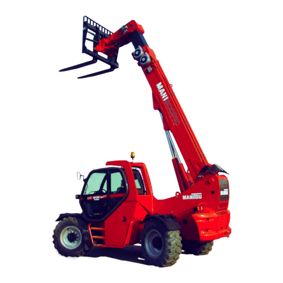
- Page 3 INTRODUCTION TO SAFETY Series MHT 10120 L M Series Series Turbo...
- Page 4 INTRODUCTION TO SAFETY...
- Page 5 INTRODUCTION TO SAFETY - INTRODUCTION TO SAFETY - - ROUGH TERRAIN FORKLIFT TRUCK GENERAL SAFETY STANDARDS - - - - - - - - - - - I - SAFETY MESSAGES - - - - - - - - - - - - - - - - - - - - - - - - - - - - - - - - - - VII - SAFETY DECALS - - - - - - - - - - - - - - - - - - - - - - - - - - - - - - - - - - - - - VIII - TABLE OF CONTENTS- - - - - - - - - - - - - - - - - - - - - - - - - - - - - - - - - - 5...
- Page 6 INTRODUCTION TO SAFETY...
- Page 7 INTRODUCTION TO SAFETY ROUGH TERRAIN FORKLIFT TRUCK GENERAL SAFETY STANDARDS...
- Page 8 Rough Terrain Forklift Safety Manual (part no. 422494) thoroughly and carefully before operating or servicing your forklift. Contact your dealer or Manitou North America, Inc. if you have any ques- tions concerning your forklift, its operation, service or parts. Keep both manuals in the literature box on the forklift available for reference.
- Page 9 INTRODUCTION TO SAFETY ROUGH TERRAIN FORKLIFT TRUCK GENERAL SAFETY STANDARDS (cont.) B.) GENERAL SAFETY PRACTICES (cont.) 7.) Where steering can be accomplished with either hand and the steering mechanism is of a type that pre- vents road reactions from causing the handwheel to spin (power steering or equivalent), steering knobs may be used.
- Page 10 INTRODUCTION TO SAFETY ROUGH TERRAIN FORKLIFT TRUCK GENERAL SAFETY STANDARDS (cont.) C.) OPERATING SAFETY RULES AND PRACTICES (cont.) 19.) Do not use a rough terrain forklift truck for opening or closing railroad car doors. 20.) In areas classified as hazardous, use only rough terrain forklift trucks approved for use in those areas. 21.) Report all accidents involving personnel, building structures, and equipment to the supervisor or as directed.
- Page 11 INTRODUCTION TO SAFETY ROUGH TERRAIN FORKLIFT TRUCK GENERAL SAFETY STANDARDS (cont.) C.) OPERATING SAFETY RULES AND PRACTICES (cont.) 46.) When attachments are used, extra care shall be taken in securing, manipulating, positioning, and trans- porting the load. Operate rough terrain forklift trucks equipped with attachments as partially loaded trucks when not handling a load.
- Page 12 ROUGH TERRAIN FORKLIFT TRUCK GENERAL SAFETY STANDARDS (cont.) D.) SUSPENDED LOADS A jib or truss boom should ONLY be used to lift and place loads when the machine is stationary and the frame is level. Transporting suspended loads must ALWAYS be done slowly and cautiously, with the boom and load as low as possible.
- Page 13 Operator and crew members have been trained in the safe use and operation of the equipment, including how to avoid electrocution. During use, no part of the equipment, load line or load will be within the minimum clearance distance specified by OSHA [10 feet (3.0 m), and more for lines rated over 50 kV] of any energized power line, and any taglines used are non-conductive.
- Page 14 All data provided in this manual is subject to production changes, addition of new models, and improved prod- uct designs. If a question arises regarding your forklift, please consult your dealer or K-D Manitou, Inc. for the latest information. When ordering service parts or requesting technical information, be prepared to quote the applicable Model/Serial Numbers.
- Page 15 SAFETY MESSAGES NOTE THE SAFETY ALERT SYMBOL (SHOWN BELOW). IT IDENTIFIES POTENTIAL HAZARDS WHICH, IF NOT AVOIDED MAY RESULT IN INJURY OR DEATH! Also, observe the safety messages places throughout this manual; providing special instructions, telling you when to take precautions and to identify potential hazards.
- Page 16 INTRODUCTION TO SAFETY SAFETY DECALS The purpose of this chapter is to introduce you to the safety messages, decals, and nameplates found on your forklift truck. The decals are identified by name, part number, location, and a brief description. (The forklift model logos, and other misc.
- Page 17 INTRODUCTION TO SAFETY SAFETY DECALS Emergency and Parking Brake - 801010 Location: near the park brake lever. Identifies the Emergency/Parking Brake Lever. Alarm Must Sound - 496162 Location: on the dash, in direct view of the operator. The backup alarm must sound when the forklift is placed in reverse gear. No Riders - 420732 Location: on the cab entrance(s), and on or near wheel fenders and engine cover.
- Page 18 INTRODUCTION TO SAFETY SAFETY DECALS Use of Frame Leveling - 801013 (Boom equipped models). Location: to the right of the operator near the hydraulic control lever. Frame leveling notice; load must be lowered. Attachment and Boom Safety - 801009 (Boom equipped models). Location: on both sides of the boom nose.
- Page 19 INTRODUCTION TO SAFETY SAFETY DECALS Gear Shift Pattern - 33460 (4-speed transmission models). Location: near the gear shift lever. Identifies the gear shift pattern of the forklift transmission. Steering Mode - 184276 (4 wheel steer equipped models). Location: near the steering mode selection lever. Identifies the steering mode selection.
- Page 20 INTRODUCTION TO SAFETY SAFETY DECALS Hydraulic Oil - 234798 or 76573 Location: on the hydraulic tank or filler cap. Identifies the hydraulic reservoir (tank) or filler cap. Hydraulic Oil - 61024 Location: on the hydraulic tank. Identifies the hydraulic reservoir (tank). Anti-Freeze - 234799 Location: on the radiator, near the radiator filler cap.
- Page 21 INTRODUCTION TO SAFETY SAFETY DECALS Attachment Warning - 421016 (Boom equipped models). Location: on the boom coupler, near where the retaining shaft is installed. Reminder to operator; install attachment retaining shaft and safety pin before operations. Hook Here - 24653 Location: at points provided on the forklift, where straps or chains may be attached to secure the forklift to a trailer during transport.
- Page 22 INTRODUCTION TO SAFETY SAFETY DECALS Acid in Battery - 801014 Location: in or near the battery storage compartment. Addresses battery hazards. Jump Start Battery - 801015 Location: in or near the battery storage compartment. Jump start instructions. Attachment Plate - 425995 Location: on the optional removeable forklift attachment.
-
Page 23: Table Of Contents
INTRODUCTION TO SAFETY Series MHT 10120 L M I N D E X I N D E X TABLE OF CONTENTS - ORIGINAL REPLACEMENT PARTS AND ATTACHMENTS - DRIVER’S OPERATING INSTRUCTIONS - Warning - General instructions - Operating instructions - Handling instructions - Load handling - MAINTENANCE INSTRUCTIONS OF THE LIFT TRUCK - BEFORE STARTING UP A NEW LIFT TRUCK... - Page 24 INTRODUCTION TO SAFETY Series MHT 10120 L M INTRODUCTION Our telescopic lift trucks have been designed to ensure simple manoeuvres and easy maintenance. Before operating the truck for the first time, the driver should read and become fully familiar with the various chapters in this manual. These instructions have been prepared to provide all the information required for proper servicing and truck operation.
- Page 25 2 - Serial N° On cab (FIG.E) FIG.E Cab N°______________________ Write all these numbers in the empty spaces. Since the MANITOU policy is to constantly improve our products, our range of telescopic lift trucks may be subject to modifications without prior notification.
- Page 26 INTRODUCTION TO SAFETY...
- Page 27 INTRODUCTION TO SAFETY...
- Page 28 INTRODUCTION TO SAFETY...
-
Page 29: Series
- Only the manufacturer knows thedetails of the lift truck design and therefore has the best technological capability to carry out maintenance. Original replacement parts are distributed exclusively by MANITOU and its dealer network. You can obtain the list of dealers by phoning the spare parts department on : TEL : 0033240091011... -
Page 30: Driver's Operating Instructions
INTRODUCTION TO SAFETY MHT 10120 L M S S eries DRIVER’S OPERA TING INSTRUCTION DRIVER’S OPERA TING INSTRUCTION Caution Whenever you see this symbol it means : Warning! Be careful! Your safety or the safety of the lift truck is at risk. - Most accidents connected with the use, maintenance and repair of the lift truck are due to non application of the basic safety instructions. - Page 31 INTRODUCTION TO SAFETY MHT 10120 L M S S eries The person in charge of the equipment must take these criteria into account when assessing whether or not a person will make a suitable driver. - Get to know the telescopic fork lift truck on the terrain where it is to be used. - Transport the load with the boom lowered and fully retracted - Position the forks at right-angles to theload to be lifted.
-
Page 32: General Instructions
INTRODUCTION TO SAFETY MHT 10120 L M S S eries A - Driver’s operating instructions. - Read the operator's manual carefully, making sure you understand it. - The operator’s manual must always be kept in the lift truck, in the place provided and in the language understood by the operator. - Page 33 INTRODUCTION TO SAFETY MHT 10120 L M S S eries D - Environment. - A lift truck operating in an area without fire extinguishing equipment must be equipped with an individual extinguisher. There are optional solutions, consult your agent or dealer.
-
Page 34: Operating Instructions
INTRODUCTION TO SAFETY MHT 10120 L M S S eries A - Driver’s operating instructions. - Wear clothes suited for driving the lift truck, avoid loose clothes. - Never operate the vehicle when hands or feet are wet or soiled with greasy sub- stances. - Page 35 INTRODUCTION TO SAFETY MHT 10120 L M S S eries Instructions - Make sure that the forward/reverse lever is in neutral. - Turn the ignition key to the position I to activate the electrical system. - Check the level on the fuel level gauge. - Turn the ignition key to position II to preheat for 15 seconds.
- Page 36 INTRODUCTION TO SAFETY MHT 10120 L M S S eries Movement instructions. - Check the transmission oil level. - Raise the forks or attachment to the transport position approximately 300 mm from the ground. - Engage the gear selected (See chapter: CONTROL AND COMMAND INSTRUMENTS in part: 2 - DESCRIPTION).
- Page 37 INTRODUCTION TO SAFETY MHT 10120 L M S S eries F - Driving the lift truck on the public highway. Safety instructions. - Lift truck drivers, driving on the public highway, must abide by the general provisions relative to highway traffic. - The lift truck must conform to the provisions of the Highway Code.
-
Page 38: Handling Instructions
INTRODUCTION TO SAFETY MHT 10120 L M S S eries A - General. - Check conformity of the accessories to the vehicle safety system calibration - Ensure the correct functioning of your lift truck’s attachments. - Do not carry out operations which exceed the capacity of the lift truck or the accessory. - It is prohibited to increase thecounterweight value in any way. - Page 39 INTRODUCTION TO SAFETY MHT 10120 L M S S eries C - Environment. - Verify that the lighting in suitable - Ensure that no person or objet is in the vicinity before raising the load. Don’t make any incorrect manoeuvres. - In the case of work near aerial lines, ensure that the safety distance is sufficient between the working area of the lift truck and the aerial line.
- Page 40 INTRODUCTION TO SAFETY MHT 10120 L M S S eries In the event of the lift truck overturning, do not try to leave the cab. DO NOT TRY TO JUMP CLEAR STAY IN THE CAB WITH YOUR SEAT BELT FASTENED. - Apply the parking brake when lifting or depositing a difficult load or when on an incline.
-
Page 41: Load Handling
INTRODUCTION TO SAFETY Series MHT 10120 L M A - Weight of load and centre of gravity. Carrying a load greater than the rated capacity for the lift truck or for the attachment is 48 in prohibited. - Before taking up a load, you must know its weight and its centre of gravity. - The load chart relating to your lift truck is valid for a weight with its centre of gravity 48 in. - Page 42 INTRODUCTION TO SAFETY MHT 10120 L M S S eries C - Taking up a high load. A load MUST NOT be picked up unless the lift truck is on a level surface (See para- graph: G - LIFT TRUCK HORIZONTALITY in the Chapter: HANDLING A LOAD). - Ensure that the forks will easily pass under the load.
- Page 43 INTRODUCTION TO SAFETY MHT 10120 L M S S eries D - Laying a high load. Under no circumstances should you lay down a load if the lift truck is not a horizontal position. (See paragraph : G - HORIZONTAL POSITION OF THE LIFT TRUCK in the chapter : LOAD HANDLING).
- Page 44 INTRODUCTION TO SAFETY MHT 10120 L M S S eries Lift truck with level corrector. - Correct the slope using the hydraulic control and check the horizontal position on the level before lifting the boom(See chapter : INSTRUMENTS AND CONTROLS in paragraph : 2 - DESCRIPTION).
-
Page 45: Maintenance Instructions Of The Lift Truck
INTRODUCTION TO SAFETY MHT 10120 L M S S eries M A I N T E N A N C E I N S T R U C T I O N S O F T H E L I F T T R U C K M A I N T E N A N C E I N S T R U C T I O N S O F T H E L I F T T R U C K A - General. - Page 46 INTRODUCTION TO SAFETY MHT 10120 L M S S eries C - Levels. - Use the recommended lubricants (Never use contaminated lubricants). - Do not fill the fuel tank when the I.C. engine is running. - Only fill up the fuel tank in areas specified for this purpose. D - Washing.
-
Page 47: Before Starting Up A New Lift Truck
INTRODUCTION TO SAFETY MHT 10120 L M S S eries BEFORE ST TING UP NEW LIFT TRUCK BEFORE ST TING UP NEW LIFT TRUCK Introduction. - Our lift trucks have been designed for easy handling by the operator and maximum ease of maintenance for the mechanic. - Page 48 INTRODUCTION TO SAFETY MHT 10120 L M S S eries Braking system. - Check by a visual examination that there are no leaks or oil oozing in the hoses, con- nections and unions. If necessary, tighten or repair the defective connections. - Also check the oil level in the tank.
-
Page 49: D E S C R I P T I On
INTRODUCTION TO SAFETY... - Page 50 INTRODUCTION TO SAFETY...
- Page 51 INTRODUCTION TO SAFETY Series MHT 10120 L M S P E C I F I C AT I O N S S P E C I F I C AT I O N S Engine (E3) - Type MERCEDES-BENZ (OM 904 LA) - Cylinders number - Number of strokes - Injection system...
- Page 52 INTRODUCTION TO SAFETY Series MHT 10120 L M Transmission - Type Hydrostatic - Type Pump and motor with variable displacement - Gear box hydraulically operated - N° of forward speeds - N° of reverse speeds - Reverser Electrohydraulic Hydraulic circuit - Lifting, tilting of telescopic boom and device - Type of pump...
- Page 53 INTRODUCTION TO SAFETY Series MHT 10120 L M Specifications - Maximum speed (19 mph) - Forward : unloaded 31 Km/h (6 mph) : Loaded 10 Km/h (19 mph) - Reverse : unloaded 31 Km/h (6 mph) : Loaded 10 km/h The maximum speed may be reduced depending on the laws which regulate road travel in different countries.
- Page 54 INTRODUCTION TO SAFETY Series MHT 10120 L M D I M E N S I O N S D I M E N S I O N S (70.9 in.) 1800 mm (129.9 in.) 3300 mm (48.4 in.) 1229 mm (233.9 in.) 5940 mm (304.7 in.)
- Page 55 INTRODUCTION TO SAFETY Series MHT 10120 L M L O A D C A PA C I T Y C H A RT L O A D C A PA C I T Y C H A RT 24 in. load center 24 in.
-
Page 56: Instruments And Controls
INTRODUCTION TO SAFETY Series MHT 10120 L M I N S T R U M E N T S A N D C O N T R O L S I N S T R U M E N T S A N D C O N T R O L S... - Page 57 INTRODUCTION TO SAFETY Series MHT 10120 L M - Driver’s seat - Seat belt - Monitoring instrument and indicator light panel - Load status control and safety device - Switch console - Light, horn and direction indicator lever - Key-switch - Casing giving access to brake fluid tank and windscreen-washing liquid - Brake fluid tank - Windscreen-washing liquid tank...
- Page 58 INTRODUCTION TO SAFETY Series MHT 10120 L M DRIVER’S SEAT (STANDARD) FOR ENHANCED COMFORT, THIS SEAT ALLOWS VARIOUS ADJUSTMENTS. WEIGHT ADJUSTMENT The seat should be adjusted to the driver’s weight with no-one sitting on it. - Take the seat notch 1 as reference. - Turn the knob 2 as appropriate to the driver’s weight.
- Page 59 INTRODUCTION TO SAFETY Series MHT 10120 L M ADJUSTING THE SEAT BACK ANGLE - Lean against the back, pull the lever and move the seat back into the position desired If the back is not held in place when adjusted, it will tip completely forward. LONGITUDINAL ADJUSTMENT - Engage the locking lever in the position desired.
- Page 60 INTRODUCTION TO SAFETY Series MHT 10120 L M MONITORING INSTRUMENT AND INDICATOR LIGHT PANEL - Red alternator excitation light. - Red engine oil pressure light. - Red engine water temperature light. - Red air filter fouling indicator light. - Red Mercedes engine alarm light. - Red engine oil level light.
- Page 61 INTRODUCTION TO SAFETY Series MHT 10120 L M D – RED AIR FILTER FOULING LIGHT The light and buzzer are activated when the air filter cartridge is fouled. Switch off the truck and make the necessary repairs (see frequency of cleaning and replacement procedures).
- Page 62 INTRODUCTION TO SAFETY Series MHT 10120 L M N – BLUE FULL BEAM HEADLIGHT LIGHT This light illuminates when the full beam headlights are in operation. O – RPM-COUNTER RPM x 100 el e ct ro ni c 0 0 5 P –...
- Page 63 INTRODUCTION TO SAFETY Series MHT 10120 L M LOAD STATUS CONTROL AND SAFETY DEVICE The load status control and safety device allows the user to check the condition of the fork-lift truck in relation to the maximum permitted load at any moment. OPERATION When the truck electrical contact is made, an automatic check is carried out.
- Page 64 INTRODUCTION TO SAFETY Series MHT 10120 L M SWITCH CONSOLE TEST A - RESET TRANSMISION B - RUNNING SELECTOR (SLOW-FAST) C - SLOW SPEED GREEN LIGHT D - FAST SPEED GREEN LIGHT E - 2 OPTIONAL CONTROL ORANGE LED (IF EQUIPPED) RESET E1 - 3 OPTIONAL CONTROL GREEN...
- Page 65 INTRODUCTION TO SAFETY Series MHT 10120 L M F - TELESCOPE FAULT RED LIGHT. When the light is on the telescope has a fault, please check the signal into the electrical box “XX” and consult your agent or dealer. G - OPTIONAL FAULT RED LIGHT. When the light flashes the optional has a fault or is manually disanabled through the optional exclusion switch (red light off - See point 17 page 20).
- Page 66 INTRODUCTION TO SAFETY Series MHT 10120 L M LIGHT, HORN AND DIRECTION INDICATOR CONTROL LEVER The lever controls the lights and horn. – Lights off, direction indicator lights not working. – Direction indicator lights signalling right. – Direction indicator lights signalling left. –...
- Page 67 INTRODUCTION TO SAFETY Series MHT 10120 L M WINDSCREEN-WASHING LIQUID TANK On the operator’s left. Remove the cap “A”; make sure that the tank is always full. Liquid to be used: water + window-cleaning detergent (use an anti-freeze in winter). ACCELERATOR PEDAL, SERVICE BRAKE AND INCHING PEDAL Pedal “B”...
- Page 68 INTRODUCTION TO SAFETY Series MHT 10120 L M PARKING BRAKE LEVER To prevent any accidental release, the lever has a safety locking system. - To engage the parking brake, pull the lever back (Position A). - To disengage the parking brake, release the lever and push it forward (Position B).
- Page 69 INTRODUCTION TO SAFETY Series MHT 10120 L M HYDRAULIC MOVEMENT CONTROLS The truck is equipped with a one lever manipulator with proportional electro-hydraulic servo control placed on the operator's right and composed of two proportional button “A” and “B” (Fig.16). - To lift the load, pull the control lever back (Fig.16/1).
- Page 70 INTRODUCTION TO SAFETY Series MHT 10120 L M OPTIONAL EXCLUSION SWITCH (accessories hydraulic block) The switch “A” has two differents positions, enabled or disabled the optional command. With the switch “B” pressed (red indicator light ON) the Optional/ accessories hydraulic block function is activated. With the switch “C”...
- Page 71 INTRODUCTION TO SAFETY Series MHT 10120 L M CEILING LIGHT The switch “A” is incorporated in the light unit. It has two positions: constant lighting and off. DOOR LOCK Outside lock “B” : To open the door, take hold of the handle and pull it outward.
- Page 72 INTRODUCTION TO SAFETY Series MHT 10120 L M TOWBAR n the rear of the truck, the towbar allows towing of a trailer. For each truck, the towing capacity is limited by the total authorised weight for travel on the public highway, the traction force and the maximum vertical stress on the tow- ing pin.
- Page 73 INTRODUCTION TO SAFETY Series MHT 10120 L M REVOLVING FLASHING LIGHT The revolving flashing light can be removed, for example to reduce the dimensions of the truck or to prevent its theft. - Unscrew the nut “A” and remove the revolving flashing light. - Protect the support “B”...
- Page 74 INTRODUCTION TO SAFETY Series MHT 10120 L M AIR CONDITIONING (OPTIONAL) A) COMPRESSOR SWITCH This switch has two positions : A0 - Off (indicator light Off) A1 - On (compressor switched on, indicator light On) N.B. The indicator light On indicates the compressor is B2 B3 C1 C2 switched on.
-
Page 75: M A I N T E N A N Ce
INTRODUCTION TO SAFETY... - Page 76 INTRODUCTION TO SAFETY...
- Page 77 INTRODUCTION TO SAFETY Series MHT 10120 L M ROUTINE MAINTENANCE FILTERING ELEMENTS AND BELTS. MANITOU 50 ÷ 100 H (WITHIN 3 MONTHS) REPLACEMENT DESCRIPTION REFERENCE (COUPON) SCHEDULE Engine oil filter 709 666 Every 500 H Air filter cartridge 723 755...
- Page 78 INTRODUCTION TO SAFETY Series MHT 10120 L M FIRST COUPON OBLIGATORY (50 ÷ 100 H WITHIN 3 MONTHS) FIRST 50HRS. MANDITORY SERVICE REQUIREMENTS LISTS OF THE OPERATION TO BE CARRIED OUT FOR THE FIRST COUPON: ENGINE - Check fuel filter - Clean air filter - Tightness check : injection power supply - Check cooling circuit...
- Page 79 INTRODUCTION TO SAFETY Series MHT 10120 L M FREQUENCY OF OPERATIONS MAINTENANCE AND LUBRICATION TABLE FREQUENCY Daily and - Engine oil level every 10 - Cooling liquid level hours - Fuel level service - Tyre pressure and wheel nut tightness - Telescopic boom slide rails Every 50 - Air filter cartridge...
- Page 80 INTRODUCTION TO SAFETY Series MHT 10120 L M FREQUENCY Every 1000 E - Air filter safety cartridge hours service E - Hydraulic oil and hydraulic oil exhaust filter cartridge or once a - Front and rear axle differential oil year if the - Transmission reduction gear box oil lift truck - Fuel tank...
- Page 81 INTRODUCTION TO SAFETY Series MHT 10120 L M COMPONENTS FOR LUBRICATION CAPACITY RECOMMENDED PRODUCT Shell: Rotella 15w40 MANITOU 500 Engine oil 4.2 gal - I.C. ENGINE + FILTER 15 + 0,8 L Citgo: C-600 15w40 (API CH4) Shell: Spirax DH80w90 0.5 gal...
- Page 82 INTRODUCTION TO SAFETY Series MHT 10120 L M - EVERY DAY EVERY 10 WORKING HOURS - CHECK THE ENGINE OIL LEVEL Before checking the oil level, make sure that the engine is stopped and that the truck is on a flat, horizontal surface. To obtain accurate information, wait for a few minutes after the engine stops so that the oil flows into the engine sump.
- Page 83 INTRODUCTION TO SAFETY Series MHT 10120 L M - CHECK THE FUEL LEVEL Place the truck on a horizontal surface with the engine stopped. To minimise the condensation due to weather conditions, the fuel tank should be kept full as far as possible. - Remove the cap “1”...
- Page 84 INTRODUCTION TO SAFETY Series MHT 10120 L M EVERY 50 WORKING HOURS - CLEANING THE AIR FILTER CARTRIDGE Slacken nut 1(Fig. B1/1) and remove cover 2 (Fig. B1/1). Slacken nut 3 (Fig. B1/2) which fixes cartridge 4 (Fig. B1/2). Clean the filter cartridge using a jet of compressed air directed from insi- de outwards.
- Page 85 INTRODUCTION TO SAFETY Series MHT 10120 L M - CLEAN AND GREASE THE TELESCOPIC BOOM SHOES Every 10 hours up to the first 50 hours and periodically every 250 hours service - Completely extend the telescopic boom. - Use a brush to apply a layer of grease (see “OILS - GREASES - FLUIDS - FUEL - FILTERS” table) to the 4 sides of the telescopic boom (fig.
- Page 86 INTRODUCTION TO SAFETY Series MHT 10120 L M - CHECK THE LEVEL OF THE BATTERY ELECTROLYTE Check the level of the electrolyte in each battery cell “1” (fig. B6/1). If necessary, add only distilled water to restore the level. Never add sulphuric acid. If frequent topping up with distilled water becomes necessary, or if the battery is subject to getting discharged, check the regulator voltage, which must be between 13 V and 14,7 V,...
- Page 87 INTRODUCTION TO SAFETY Series MHT 10120 L M GREASE POINTS To be carried out weekly, if the lift truck has been operated for less than 50 hours during the week. In the event of prolonged use in an extremely dusty or oxidising atmosphere, reduce this interval to 10 working hours or every day.
- Page 88 INTRODUCTION TO SAFETY Series MHT 10120 L M Fig. B11/1 Fig. B10 Fig. B8 - B9 Fig. B12/2 Fig. B12/1 Fig. B11/2 Fig. B13/2 Fig. B13/1...
- Page 89 INTRODUCTION TO SAFETY Series MHT 10120 L M - Grease tilting bushes of front axle “1-2” (Fig. B17/1 - B17/2). Grease tilting bushes of rear axle “3-4” (Fig. B17/3 - B17/4). - Grease journal and universal the cardan shaft on the rear side “1” (fig. B18/1) and front side “1” (fig.
- Page 90 INTRODUCTION TO SAFETY Series MHT 10120 L M - EVERY 250 WORKING HOURS - CHECK THE OIL LEVEL OF THE FRONT AND REAR AXLE DIFFERENTIAL. Place the truck on a horizontal surface with the engine stopped. Check the oil level of the front axle differential. Remove the cap “1”...
- Page 91 INTRODUCTION TO SAFETY Series MHT 10120 L M CHECKING THE POLY-V RIBBED BELT TENSION CHECKING THE POLY-V RIBBED BELT TENSION Open the engine hood and remove crank case 1 C4/1. Check for the presence of damage on ribbed belt 2 C4/2 moving one section at a time;...
- Page 92 INTRODUCTION TO SAFETY Series MHT 10120 L M - EVERY 500 WORKING HOURS - CHANGING THE TRANSMISSION OIL FILTER Use a collar wrench to remove the transmission oil filter “1” (fig. D1/1) and throw it away together with the gasket. Clean the filter support with a clean cloth which does not leave threads.
- Page 93 INTRODUCTION TO SAFETY Series MHT 10120 L M - CHANGE THE OIL IN THE FRONT AND REAR AXLE DIFFERENTIAL Put the truck on a horizontal surface with the engine off and the differential oil still warm. Drain the oil from the front axle differential. Place a can under drain plugs “2”...
- Page 94 INTRODUCTION TO SAFETY Series MHT 10120 L M - REPLACE THE POLY-V RIBBED BELT Replace the ribbed V-belt if one of the following types of damage illu- strated is present ( C Take great care while disassembling and assembling the ribbed V- Take great care while disassembling and assembling the ribbed V- belt, keeping the fingers well out of the area between the pulley belt, keeping the fingers well out of the area between the pulley...
- Page 95 INTRODUCTION TO SAFETY Series MHT 10120 L M - CHECKING/ADJUSTING THE VALVE CLEARANCE Operation to be performed the first time on reaching 500 hours of service, periodically every 1500 hours of service. Adjust the valve clearance with the engine cold. Adjust the valve clearance with the engine cold.
- Page 96 INTRODUCTION TO SAFETY Series MHT 10120 L M Layout of cylinders and valves (Fig. D8/2) = suction valve = discharge valve = handwheel side FIG. D8/2 Checking/adjusting the clearance of the valves Measure the valve clearance between the rocker arm and the valve stem (discharge valve) or the valves bridge (suction valve) using a thickness gauge (arrow).
- Page 97 INTRODUCTION TO SAFETY Series MHT 10120 L M - CHANGE THE OIL AND THE ENGINE FILTER Change the oil only with the engine at operating temperature. Engine oil filter Unscrew the threaded oil filter cap using a 36mm pipe wrench Drain the oil out of the filter casing.
- Page 98 INTRODUCTION TO SAFETY Series MHT 10120 L M Change the engine oil Pour fresh oil into the engine through filler plug “5” (fig. D9/3), until the level reaches the max. notch on level rod “6” (Fig. D9/3). Start up the engine at minimum speed and observe the oil low pressure indicator.
- Page 99 INTRODUCTION TO SAFETY Series MHT 10120 L M - EVERY 1000 WORKING HOURS - REPLACING THE AIR FILTER SAFETY CARTRIDGE Dismantle the air filter cartridge (see Chapter: D Remove the air filter safety cartridge “1” (Fig. E1) and replace it with a new one.
- Page 100 INTRODUCTION TO SAFETY Series MHT 10120 L M - CHANGING OIL IN FRONT AND REAR WHEEL FINAL DRIVES Empty the front wheel final drivers. Position the truck on level ground, with the engine off and the oil in the final drives still hot. Make sure the drain and level plug “1”...
- Page 101 INTRODUCTION TO SAFETY Series MHT 10120 L M - EMPTYING AND CLEANING THE FUEL TANK. During this operation, do not smoke and do not approach with naked lights Place the truck on a horizontal surface; the engine must be stopped. - Make a visual and manual check on the parts on the fuel cir- cuit and in the tank which may leak.
- Page 102 INTRODUCTION TO SAFETY Series MHT 10120 L M - EVERY 1500 WORKING HOURS -CLEAN THE FUEL PREFILTER CARTRIDGE - Open the tank cap to discharge the excess pressure inside the system. - Clean the outside of the fuel prefilter, after taking care to cover the ducts, hoses and cables which may be present under the prefilter.
- Page 103 INTRODUCTION TO SAFETY Series MHT 10120 L M - REPLACE THE FUEL PREFILTER CARTRIDGE WITH WATER SEPARATOR - Turn knob “1” (Fig. F2/1) clockwise to close the fuel flow dur- ing cartridge replacement. - Open drainage valve “2” (Fig. F2/2) and bleed screw “3” (Fig. F2/1) and collect the water-fuel mixture flowing out of the filter element in a container.
- Page 104 INTRODUCTION TO SAFETY Series MHT 10120 L M - REPLACE THE FUEL FILTER CARTRIDGE Open the tank cap to prevent overpressure from building up insi- Unscrew threaded cap “1” (Fig. F3) of the fuel filter using a pipe wrench. Remove threaded cap “1” (Fig. F3) together with cartridge “3” (Fig.
- Page 105 INTRODUCTION TO SAFETY Series MHT 10120 L M - CHANGE THE COOLING LIQUID IN THE COOLING SYSTEM ATTENTION: Open the cap for filling the cooling system only if the temperature of the liquid is less than 90°C/194°F. In any case, it is obligatory to use protective gloves and clothing as well as safety goggles.
- Page 106 INTRODUCTION TO SAFETY Series MHT 10120 L M Place a container large enough for the quantity of liquid to be col- lected, under the radiator drainage screw “4” (Fig. F4/4). Unscrew the radiator drainage screw “4” (fig. F4/4) (in the lower part of the radiator) and drain out the cooling liquid.
-
Page 107: G - Occasional Maintenance
INTRODUCTION TO SAFETY Series MHT 10120 L M - OCCASIONAL MAINTENANCE - CHANGE A WHEEL In the event of a wheel being changed on the public highway, make sure of the following points : - Stop the lift truck, if possible on even and hard ground. - To pass on stop of lift truck (See chapter : DRIVING INSTRUCTIONS in paragraph : 1 - OPERATING AND SAFETY INSTRUCTIONS). - Page 108 INTRODUCTION TO SAFETY Series MHT 10120 L M TOW THE LIFT TRUCK DANGER! NO BRAKES! The forklift must be fully supported by chocks and/or a large towing vehicle and tow bar before releasing the brakes! Tow the lift truck for a short distance with slow speed. - Shut down engine - Put the forward/reverse lever in neutral position - Release the parking brake...
- Page 109 INTRODUCTION TO SAFETY Series MHT 10120 L M - SLING THE LIFT TRUCK - Take into account the position of the lift truck gravity center for lifting (Fig. G3/1). - Place the hooks in the fastening points provided (Fig. G3/2 and G3/3). FIG.
- Page 110 INTRODUCTION TO SAFETY Series MHT 10120 L M - TRANSPORT THE LIFT TRUCK ON A PLATFORM To carry the machine respect the circulation laws. Ensure that the safety instructions connected to the platform are respected before the loading of the lift truck and that the driver of the means of transport is informed about the dimensions and the weight of the lift truck (See chapter : CHARACTERISTICS in paragraph : 2 - DESCRIPTION).
- Page 111 INTRODUCTION TO SAFETY Series MHT 10120 L M - ADJUST THE FRONT HEADLAMPS Recommended setting(As per standard ECE-76/756 76/761 ECE20) Set to - 2% of the dipped beam in relation to the horizontal line of the headlamp. Adjusting procedure - Place the lift truck unloaded and in the transport position and perpendicular to a white wall on flat, level ground (Fig.
- Page 112 INTRODUCTION TO SAFETY...
- Page 113 INTRODUCTION TO SAFETY...
- Page 114 INTRODUCTION TO SAFETY...
-
Page 115: Electrical System
INTRODUCTION TO SAFETY MHT 10120 L M S S eries ELECTRICAL SYSTEM Starter motor. The starter motor is installed on the left of the engine and no maintenance is required except cleaning and tightening of the terminals. If the starter motor does not work properly, consult your agent or dealer. Alternator. - Page 116 INTRODUCTION TO SAFETY MHT 10120 L M S S eries FUSE AND RELA FUSE AND RELA The electric circuit is protected by fuses mounted in the fuse box. To change a fuse, remove it and replace it with a new one with the same quality and calibration values. If a power failure occurs, check all the fuses and verify if a short-circuit has occurred.
- Page 117 INTRODUCTION TO SAFETY Series MHT 10120 L M LIGHTING LIGHTING A blown bulb must be changed immediately. Do not handle a new bulb with bare or dirty fingers. Any traces of grease, oil or sweat will evaporate when the bulb is hot and stain the reflector. Never touch or attempt to polish the reflector.
- Page 118 INTRODUCTION TO SAFETY MHT ELECTRIC SYSTEM USERS' LEGEND F18b 5 Reverse relay diode FLA1 19 Front work lights F19a 20 1200 rpm solenoid valve fuse FLA2 19 Front work lights Code Page Function F19b 20 “30” antitheft fuse FLB1 19 Boom top work light 5 Reverse engaged buzzer F20a 9 Anti-tilting fuse...
- Page 119 INTRODUCTION TO SAFETY 17 Manoeuvres manipulator 13 Air conditioner compressor 8 Reverse solenoid valve 10 Levelling switch 13 Cab aeration fan motor 10 LH levelling solenoid valve 11 Air filter pressure switch 21 Pneumatic seat 9 Anti-tilting solenoid valve 6 Ceiling light switch 15 Top wiper motor 10 RH levelling solenoid valve 11 Battery optical indicator...
- Page 120 INTRODUCTION TO SAFETY TAVOLA MHT 10120 M SERIES DISTRIBUTORE REXROTH (12-2005) / MHT 10120 M SERIES DISTRIBUTOR REXROTH (12-2005) TABLE Denominazione TITOLO Name: TITLE...
- Page 121 INTRODUCTION TO SAFETY LISTA FOGLI \ INDEX Tavola Descrizione Tavola Descrizione Table Description Table Description TITOLO / TITLE LEGENDA FOGLI / TABLE NOTE LEGENDA COLORI / COLOUR NOTE QUADRO AVVIAMENTO / STARTING ENGINE SELETTORE LUCI MILITARE - LUCI OSCURATE / WAR LIGHT'S SELECTOR DEVIO LUCI, EMERGENZA ED INTERMITTENZA / LIGHT'S SELECTOR, HAZARD FANALERIA / LIGHTS DEVIO MARCE / FORWARD AND REVERSE GEAR...
- Page 122 INTRODUCTION TO SAFETY LEGENDA / DESCRIPTION R1.5 SEGNALE ROSSO sez 1.5 mm DIRETTO A PAG 2 COLONNA 5 RED SIGNAL sect. 1.5 mm LEADING TO PAGE 2 COLUMN 5 R1.5 SEGNALE ROSSO sez 1.5 mm PROVENIENTE DA PAG 1 COLONNA 7 RED SIGNAL sect.
- Page 123 INTRODUCTION TO SAFETY TAVOLA MHT 10120 M SERIES DISTRIBUTORE REXROTH (12-2005) / MHT 10120 M SERIES DISTRIBUTOR REXROTH (12-2005) TABLE Denominazione QUADRO AVVIAMENTO Name: STARTING ENGINE...
- Page 124 INTRODUCTION TO SAFETY TAVOLA MHT 10120 M SERIES DISTRIBUTORE REXROTH (12-2005) / MHT 10120 M SERIES DISTRIBUTOR REXROTH (12-2005) TABLE Denominazione SELETTORE LUCI MILITARE / LUCI SCRUPOLARE Name: WAR LIGHT'S SELECTOR...
- Page 125 INTRODUCTION TO SAFETY TAVOLA MHT 10120 M SERIES DISTRIBUTORE REXROTH (12-2005) / MHT 10120 M SERIES DISTRIBUTOR REXROTH (12-2005) TABLE Denominazione DEVIO LUCI, EMERGENZA ED INTERMITTENZA Name: LIGHT'S SELECTOR, HAZARD...
- Page 126 INTRODUCTION TO SAFETY TAVOLA MHT 10120 M SERIES DISTRIBUTORE REXROTH (12-2005) / MHT 10120 M SERIES DISTRIBUTOR REXROTH (12-2005) TABLE Denominazione FANALERIA Name: LIGHTS...
- Page 127 INTRODUCTION TO SAFETY TAVOLA MHT 10120 M SERIES DISTRIBUTORE REXROTH (12-2005) / MHT 10120 M SERIES DISTRIBUTOR REXROTH (12-2005) TABLE Denominazione DEVIO MARCE Name: FOWARD AND REVERSE GEAR...
- Page 128 INTRODUCTION TO SAFETY TAVOLA MHT 10120 M SERIES DISTRIBUTORE REXROTH (12-2005) / MHT 10120 M SERIES DISTRIBUTOR REXROTH (12-2005) TABLE Denominazione ANTI-RIBALTAMENTO E TERGI Name: ANTI-OVERTURNING; WINDSCREEN...
- Page 129 INTRODUCTION TO SAFETY TAVOLA MHT 10120 M SERIES DISTRIBUTORE REXROTH (12-2005) / MHT 10120 M SERIES DISTRIBUTOR REXROTH (12-2005) TABLE Denominazione MANIP. LIVELLAMENTO E LAMPADA ROTANTE Name: LEVELLING AND WORKING LAMP...
- Page 130 INTRODUCTION TO SAFETY TAVOLA MHT 10120 M SERIES DISTRIBUTORE REXROTH (12-2005) / MHT 10120 M SERIES DISTRIBUTOR REXROTH (12-2005) TABLE Denominazione CHECK E INDICATORI OTTICI Name: CHECK AND WARNING LIGHTS...
- Page 131 INTRODUCTION TO SAFETY TAVOLA MHT 10120 M SERIES DISTRIBUTORE REXROTH (12-2005) / MHT 10120 M SERIES DISTRIBUTOR REXROTH (12-2005) TABLE Denominazione STRUMENTAZIONE Name: INSTRUMENTATION...
- Page 132 INTRODUCTION TO SAFETY TAVOLA MHT 10120 M SERIES DISTRIBUTORE REXROTH (12-2005) / MHT 10120 M SERIES DISTRIBUTOR REXROTH (12-2005) TABLE Denominazione CONDIZIONATORE CABINA Name: CONDITIONER...
- Page 133 INTRODUCTION TO SAFETY TAVOLA MHT 10120 M SERIES DISTRIBUTORE REXROTH (12-2005) / MHT 10120 M SERIES DISTRIBUTOR REXROTH (12-2005) TABLE Denominazione SISTEMA RAFFREDDAMENTO OLIO Name: OIL COOLING SYSTEM...
- Page 134 INTRODUCTION TO SAFETY TAVOLA MHT 10120 M SERIES DISTRIBUTORE REXROTH (12-2005) / MHT 10120 M SERIES DISTRIBUTOR REXROTH (12-2005) TABLE Denominazione STERZATE E ALLINEAMENTO PONTI Name: STEERING CYRCUIT...
- Page 135 INTRODUCTION TO SAFETY TAVOLA MHT 10120 M SERIES DISTRIBUTORE REXROTH (12-2005) / MHT 10120 M SERIES DISTRIBUTOR REXROTH (12-2005) TABLE Denominazione CENTRALINA MERCEDES Name: MERCEDES ELECTRONIC DEVICE...
- Page 136 INTRODUCTION TO SAFETY TAVOLA MHT 10120 M SERIES DISTRIBUTORE REXROTH (12-2005) / MHT 10120 M SERIES DISTRIBUTOR REXROTH (12-2005) TABLE Denominazione MANIPOLATORE 4 POS. E 2a-3a USCITA BRACCIO Name: MANIPULATOR AND 2ND-3RD BOOM'S EXIT...
- Page 137 INTRODUCTION TO SAFETY TAVOLA MHT 10120 M SERIES DISTRIBUTORE REXROTH (12-2005) / MHT 10120 M SERIES DISTRIBUTOR REXROTH (12-2005) TABLE Denominazione SET-RESET MANOVRE IDRAULICHE Name: HYDRAULIC MOVEMENT SET-RESET...
- Page 138 INTRODUCTION TO SAFETY TAVOLA MHT 10120 M SERIES DISTRIBUTORE REXROTH (12-2005) / MHT 10120 M SERIES DISTRIBUTOR REXROTH (12-2005) TABLE Denominazione ANTIFURTO, AUTORADIO E FARI DI LAVORO Name: ANTI-THIEFT, RADIO WORKING LIGHTS...
- Page 139 INTRODUCTION TO SAFETY TAVOLA MHT 10120 M SERIES DISTRIBUTORE REXROTH (12-2005) / MHT 10120 M SERIES DISTRIBUTOR REXROTH (12-2005) TABLE Denominazione ANTIFURTO, AUTORADIO Name: ANTI-THIEFT, RADIO...
- Page 140 INTRODUCTION TO SAFETY TAVOLA MHT 10120 M SERIES DISTRIBUTORE REXROTH (12-2005) / MHT 10120 M SERIES DISTRIBUTOR REXROTH (12-2005) TABLE Denominazione CESTELLO + BENNA MIX Name: BASKET + MIXING BUCKET...
- Page 141 INTRODUCTION TO SAFETY HYDRAULIC SYSTEM...
- Page 142 INTRODUCTION TO SAFETY MHT 10120 L M S S eries KEY TO MOVEMENT HYDRAULIC SYSTEM DIAGRAM = Pressure booster COLLET = Manifold = Locking and balancing valve = Double piloted relief valve = Piloted relief valve = Directional control valve D.F.
- Page 143 INTRODUCTION TO SAFETY S S eries MHT 10120 L M MOVEMENT HYDRAULIC SYSTEM DIAGRAM (105x80x3973) (135x95x510) (135x95x510) (180x115x1540) 300b 300b 300b 300b (105x75x1095) 300b I.D.(P) I.D.(LS) 300b 300b D.F. E.V.S. V.L.* (140x65x170) 0,7 LITRE 23 BAR R.F.S. Ø 1.2 Ø 1.2 200bar E.C.L.
- Page 144 INTRODUCTION TO SAFETY S S eries MHT 10120 L M KEY TO BRAKE/STEERING SYSTEM DIAGRAM COLLET = Manifold D. (S) = S connection of directional control valve D. (SX) = SX connection of directional control valve = Solenoid valve F.S. = Parking brake control cylinder FDAR = Rear axle disk brake...
- Page 145 INTRODUCTION TO SAFETY S S eries MHT 10120 L M BRAKE/STEERING SYSTEM DIAGRAM VSLR COLLET.2 COLLET.3 PH (G) FDAR FDAV VCLR D(S) D(SX) V.D. V.D. I.D. FDAV FDAR 180 bar COLLET.3...
- Page 146 INTRODUCTION TO SAFETY S S eries MHT 10120 L M KEY TO TRANSMISSION HYDRAULIC SYSTEM DIAGRAM COLLETTORE = Manifold = Directional control valve = Flow divider F.A. = Intake filter F.R. = Drain filter I.D. = Power steering unit = Control lever = Brake pump M.I.
- Page 147 INTRODUCTION TO SAFETY TRANSMISSION HYDRAULIC SYSTEM DIAGRAM 512 bar 512 bar 465 bar 32 bar MC + RFS + M PH (G) VSLR M.V. 3bar COLETTORE 1 COLETTORE 2 COLETTORE 3 3bar 2bar VSLR D.F. V.M. MICRONS...
- Page 148 INTRODUCTION TO SAFETY...
- Page 149 INTRODUCTION TO SAFETY...
- Page 150 INTRODUCTION TO SAFETY...
-
Page 151: Introduction
For subsequent requests for implementation of machine functions using other accessories, before starting up the machine, the user must request inspection for suitability for use by an authorized MANITOU technician, who will check the correct working and updating of the documentation necessary for using the new accessory. -
Page 152: General Recommendations For Use Of A Lift Truck
INTRODUCTION TO SAFETY Series MHT 10120 L M GENERAL RECOMMENDATIONS FOR USE OF A LIFT-TRUCK GENERAL RECOMMENDATIONS FOR USE OF A LIFT-TRUCK WHEN YOU SEE THIS SYMBOL : CAUTION ! TAKE CARE ! YOUR SAFETY OR THAT OF THE TRUCK IS AT STAKE. - Page 153 INTRODUCTION TO SAFETY Series MHT 10120 L M Using the machine outfitted with hoist When all the green, yellow and red LEDs (Fig. A-Ref. 1) on the truck stabilization control instrument light up, the hydraulic commands are automatically blocked. Only the boom retraction, fork inclination and hoist rope descent commands are authorized.
-
Page 154: Accessory Without Hydraulic System And Manual Locking
INTRODUCTION TO SAFETY Series MHT 10120 L M ACCESSORY WITHOUT HYDRAULIC SYSTEM AND MANUAL LOCKING ACCESSORY WITHOUT HYDRAULIC SYSTEM AND MANUAL LOCKING ENGAGING THE ACCESSORY - Check that the accessory is in a position which simplifies connection of the snap coupling. If it is badly positioned, take the necessary precautions to move it in the conditions of maximum safety. -
Page 155: Accessory Without Hydraulic System And Hydraulic Locking (Optional)
INTRODUCTION TO SAFETY Series MHT 10120 L M ACCESSORY WITHOUT HYDRAULIC SYSTEM AND HYDRAULIC LOCKING (OPTIONAL) ACCESSORY WITHOUT HYDRAULIC SYSTEM AND HYDRAULIC LOCKING (OPTIONAL) ENGAGING THE ACCESSORY - Check that the accessory is in a position which simplifies connection of the snap coupling. If it is badly positioned, take the necessary precautions to move it in the conditions of maximum safety. -
Page 156: Accessory With Hydraulic System And Manual Locking (Optional)
INTRODUCTION TO SAFETY Series MHT 10120 L M ACCESSORY WITH HYDRAULIC SYSTEM AND MANUAL LOCKING (OPTIONAL) ACCESSORY WITH HYDRAULIC SYSTEM AND MANUAL LOCKING (OPTIONAL) ENGAGING THE ACCESSORY - Check that the accessory is in a position which simplifies connection of the snap coupling. If it is badly positioned, take the necessary precautions to move it in the conditions of maximum safety. -
Page 157: Accessory With Hydraulic System And Hydraulic Locking (Optional)
INTRODUCTION TO SAFETY Series MHT 10120 L M ACCESSORY WITH HYDRAULIC SYSTEM AND HYDRAULIC LOCKING (OPTIONAL) ACCESSORY WITH HYDRAULIC SYSTEM AND HYDRAULIC LOCKING (OPTIONAL) ENGAGING THE ACCESSORY - Check that the accessory is in a position which simplifies connection of the snap coupling. If it is badly positioned, take the necessary pre- cautions to move it in the conditions of maximum safety. - Page 158 INTRODUCTION TO SAFETY...
Need help?
Do you have a question about the M Turbo Series and is the answer not in the manual?
Questions and answers