IFM SI 5000, SI 5001, SI 5010, SI5011, SI 5006 - Sensor Quick Manual
- Manual (2 pages) ,
- Operating instructions manual (13 pages)
Advertisement
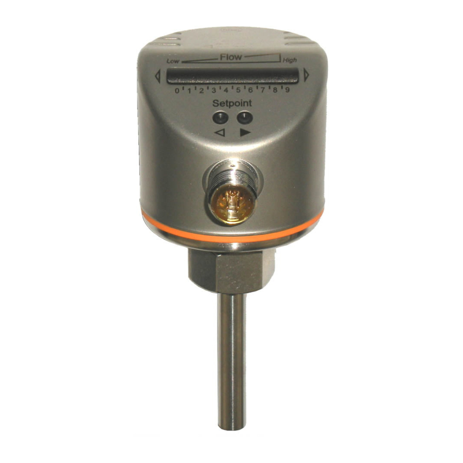
Visual Indicators and Controls


Green LEDs indicate current flow
Orange LED indicates setpoint, output closed
Red LED indicates setpoint outpoint open

LED 9 flashing indicates current flow is above the taught flow range

LED 0 flashing indicates current flow is much below the taught flow range

Pushbuttons for automatic / manual setting
A short circuit is indicated when the display alternately changes between all red LEDs and the current flow indication.
If no LEDs are lit, check supply voltage (must be >19 V).
Set-up and scaling the display
The sensor is factory preset to monitor the range 5...100 cm / sec of water and setpoint position of LED 7. If the adjustments are required, follow these instructions.
High flow adjustment
This adjustment calibrates the sensor so that all LEDs are lit when the maximum flow velocity is reached.
| 1 | Allow the maximum flow velocity to circulate through the system and keep it constant. |
| 2 | Press the  pushbutton and hold. LED 9 lights, after 5 seconds it flashes. pushbutton and hold. LED 9 lights, after 5 seconds it flashes. |
| 3 | Release the pushbutton. |
Low flow adjustment
If the sensor is used in media other than water, a low flow adjustment should be performed. This adjustment must only be carried out after a high flow adjustment.
| 1 | Allow the minimum flow velocity to circulate through the system (or ensure no flow if that is the minimum condition) and keep it constant. |
| 2 | Press the  pushbutton and hold. LED 0 lights, after 5 seconds it flashes. pushbutton and hold. LED 0 lights, after 5 seconds it flashes. |
| 3 | Release the pushbutton. |
Setpoint adjustment
If a faster response time is desired (low setpoint = fast response with rising flow, high setpoint = fast response time with falling flow), adjust the setpoint as shown.
| 1 | Briefly press either pushbutton or and release. The setpoint LED flashes. |
| 2 | Press the pushbutton or as often as required. The setpoint shifts by one LED position in the direction shown by the pushbutton. |
Output configuration
Factory default of the switching output is normally open (output turns on when flow is above setpoint). The output can be changed to normally closed as follows.
| 1 | Press the pushbutton and hold. LED 0 lights, after 5 seconds it flashes. |
| 2 | Continue to hold the pushbutton, after 10 seconds the current output setting is displayed (LEDs 5...9 orange = normally open output). |
| 3 | Continue to hold the pushbutton, after 15 seconds LEDs 0...4 flash orange. Release the pushbutton. The output has been changed to normally closed. |
Return all settings to factory default
| 1 | Press the pushbutton and hold. LED 9 lights, after 5 seconds it flashes. |
| 2 | Continue to hold the pushbutton, after 15 seconds LEDs 0...9 flash orange. Release the pushbutton. All settings have been returned to factory default. |
ifm efector inc.
TEL: 800-441-8246 • FAX: 800-329-0436
www.ifmefector.com
3/08
Lit. No.: B10308
Documents / Resources
References

Download manual
Here you can download full pdf version of manual, it may contain additional safety instructions, warranty information, FCC rules, etc.
Download IFM SI 5000, SI 5001, SI 5010, SI5011, SI 5006 - Sensor Quick Manual
Advertisement


Need help?
Do you have a question about the SI 5000 and is the answer not in the manual?
Questions and answers