Table of Contents
Advertisement
Quick Links
Advertisement
Table of Contents

Related Manuals for IFM SBY2 Series


Summary of Contents for IFM SBY2 Series
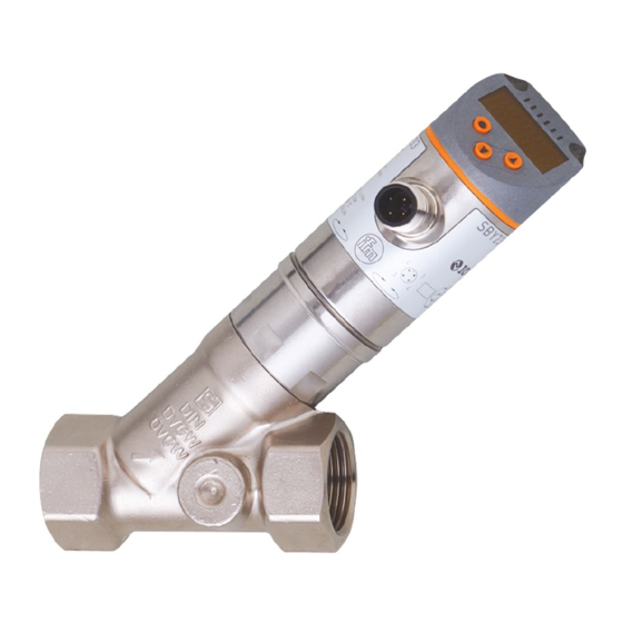
- Page 1 Operating instructions Mechatronic flow sensor SBY2xx SBG2xx SBN2xx...
-
Page 2: Table Of Contents
SBY2xx SBG2xx SBN2xx Mechatronic flow sensor Contents Preliminary note ............. Symbols used . - Page 3 Mechatronic flow sensor SBY2xx SBG2xx SBN2xx 10.2.5.1 Reading minimum values / maximum values......24 11 Operation ..............25 11.1 Process value display .
-
Page 4: Preliminary Note
SBY2xx SBG2xx SBN2xx Mechatronic flow sensor 1 Preliminary note You will find instructions, technical data, approvals and further information using the QR code on the unit / packaging or at www.ifm.com. 1.1 Symbols used Requirement Instructions Reaction, result [...] Designation of keys, buttons or indications... -
Page 5: Safety Instructions
Mechatronic flow sensor SBY2xx SBG2xx SBN2xx 2 Safety instructions • The unit described is a subcomponent for integration into a system. – The system architect is responsible for the safety of the system. – The system architect undertakes to perform a risk assessment and to create documentation in accordance with legal and normative requirements to be provided to the operator and user of the system. -
Page 6: Intended Use
SBY2xx SBG2xx SBN2xx Mechatronic flow sensor 3 Intended use The unit monitors liquid media (water, glycol solutions, industrial oils, coolants). It detects the process categories volume flow (volumetric flow quantity/time) and medium temperature. ATTENTION Frost formation of the medium. w The sensor may be damaged. u Ensure that the medium in the sensor does not freeze during operation and transport. -
Page 7: Function
Mechatronic flow sensor SBY2xx SBG2xx SBN2xx 4 Function • The unit detects the flow rate according to the principle of differential pressure by means of a permanent magnet and a measuring cell. • As additional process value the unit detects the medium temperature. •... -
Page 8: Analogue Output
SBY2xx SBG2xx SBN2xx Mechatronic flow sensor Process value Time Upper limit value Lower limit value Hysteresis Window area Fno: Window function NO (normally open) Fnc: Window function NC (normally closed) Fig. 2: Window function When set to the window function the upper limit value [FH] and the lower limit value [FL] are defined. -
Page 9: Temperature Monitoring
Mechatronic flow sensor SBY2xx SBG2xx SBN2xx 4.4.2 Temperature monitoring [mA] FOU=On 21,5 FOU=OFF [°C] [°F] Fig. 4: Characteristics of the analogue output according to the standard IEC 6094752, temperature Analogue signal MAW: Initial value of the measuring range Temperature MEW: Final value of the measuring range Measuring range Above the display range Display range... -
Page 10: Volumetric Flow Monitoring
SBY2xx SBG2xx SBN2xx Mechatronic flow sensor 4.5.1 Volumetric flow monitoring [% FrP1] FOU = ON 130 = FrP1 FOU = OFF 0 FEP1 MEW 120 130 [% MEW] Fig. 5: Output characteristic frequency output, flow rate Frequency signal MAW: Initial value of the measuring range Flow MEW: Final value of the measuring range... -
Page 11: Io-Link
IO-Link is an internationally standardised IO technology (IEC 61131-9) for communicating with sensors and actuators. General information about IO-Link can be found at io-link.ifm. IO Device Description (IODD) with all parameters and process data of the unit can be found at documentation.ifm.com. -
Page 12: Mounting
SBY2xx SBG2xx SBN2xx Mechatronic flow sensor 5 Mounting CAUTION During installation or in case of a fault (e.g. housing damage) media under high pressure or hot media can leak from the system. w Risk of injury caused by pressure or burns. u Ensure that the system is free of pressure during installation. -
Page 13: Mounting Accessories
Fig. 10: Installation with mounting plate threaded hole M8 (depth 6 mm) on the bottom side of the unit Information about available accessories at www.ifm.com 5.4 Installation in case of medium containing dirt u Use a 200-micron filter in front of the inlet (IN). -
Page 14: Electrical Connection
SBY2xx SBG2xx SBN2xx Mechatronic flow sensor 6 Electrical connection The device must be connected by a qualified electrician. Observe the national and international regulations for the installation of electrical equipment. Voltage supply according to EN 50178, SELV, PELV. u Disconnect power. u Connect the unit as follows: OUT2 OUT1/IO-Link Fig. 12: Wiring diagram (colours to DIN EN 60947-5-2) -
Page 15: Operating And Display Elements
Mechatronic flow sensor SBY2xx SBG2xx SBN2xx 7 Operating and display elements Switching status LED for OUT1 Switching status LED for OUT2 Process value in the indicated unit of measurement * 4-digit alphanumeric display Keys for changing views and parameter setting Fig. 14: Operating and display elements * l/min;... -
Page 16: Menu
SBY2xx SBG2xx SBN2xx Mechatronic flow sensor 8 Menu The figures in which the menus are displayed show the parameters that can be set on the unit by key input. These parameters and other functions are also available via the IO-Link interface. 8.1 Menu overview Use the operating keys to navigate from the process value display to the main menu and from there to the submenus. - Page 17 Mechatronic flow sensor SBY2xx SBG2xx SBN2xx Main menu - - - - Fig. 17: Extended functions [EF] menu Hno Hnc Fno Fnc FRQ Hno Hnc Fno Fnc Lmin MEdi OIL.2 FOU1 FOU2 SEL1 FLOW TEMP SEL2 FLOW TEMP Fig. 18: Basic settings [CFG] menu For SBN2xx units Lo.T 1234...
- Page 18 SBY2xx SBG2xx SBN2xx Mechatronic flow sensor coLr GrEn r1ou G1ou r2ou G2ou rd3 OFF SELd FLOW TEMP Fig. 20: Display settings [DIS] menu...
-
Page 19: Set-Up
Mechatronic flow sensor SBY2xx SBG2xx SBN2xx 9 Set-up After power on and expiry of the power-on delay time, the unit is in the normal operating mode. It carries out its measurement and evaluation functions and generates output signals according to the set parameters. -
Page 20: Parameter Setting
For parameter setting via the IO-Link interface, you need suitable parameter setting software and the IO Device Description (IODD) for the unit. • IODD, parameter setting software and information on IO-Link at io-link.ifm. Notes on parameter setting Ò Manual of the parameter setting software. •... -
Page 21: Parameter Setting Via The Unit Keys
Mechatronic flow sensor SBY2xx SBG2xx SBN2xx 10.2 Parameter setting via the unit keys CAUTION If the medium temperature is above 50 °C (122 °F), parts of the housing can increase in temperature to over 65 °C (149 °F). w Risk of burns u Do not touch the device with your hands. -
Page 22: Setting The Output Functions
SBY2xx SBG2xx SBN2xx Mechatronic flow sensor 10.2.3 Setting the output functions The parameters for flow monitoring and temperature monitoring are set in the same way. The prerequisite is that the process value for OUTx has first been defined via [SELx]. 10.2.3.1 Limit monitoring OUTx / hysteresis function u Select the CFG menu. -
Page 23: Display Colour Setting
Select the CFG menu. u Select [MEdi] and set the medium: • H2O: Water • OIL: Ò Technical data sheet at documentation.ifm.com OIL2: Ò Technical data sheet at • documentation.ifm.com 10.2.4.4 Output logic u Select the CFG menu. u Select [P-n] and set PnP or nPn. -
Page 24: Lock / Unlock
SBY2xx SBG2xx SBN2xx Mechatronic flow sensor – OU: The analogue signal still corresponds to the measured value. • Frequency output – On: The frequency signal goes to 130 % of FrPx. – OFF: The frequency signal goes to 0 Hz. –... -
Page 25: Operation
Mechatronic flow sensor SBY2xx SBG2xx SBN2xx 11 Operation 11.1 Process value display It is possible to switch between different process value indications during operation: u Press [▲] or [▼]. w The display changes between the standard indication with set standard unit of measurement and other views. -
Page 26: Troubleshooting
If several diagnostic events occur simultaneously, only the diagnostic message of the event with the highest priority is displayed. If the measured temperature value fails, the process value for flow rate is still available. Additional diagnostic functions are available via IO-Link Ò IO-Link interface description at documentation.ifm.com. 12.1 Error messages Display Problem/remedy Unit faulty / malfunction u Replace the unit. -
Page 27: Maintenance, Repair And Disposal
Mechatronic flow sensor SBY2xx SBG2xx SBN2xx 13 Maintenance, repair and disposal The operation of the unit is maintenance-free. Only the manufacturer is allowed to repair the unit. u After use dispose of the device in an environmentally friendly way in accordance with the applicable national regulations. -
Page 28: Factory Settings
SBY2xx SBG2xx SBN2xx Mechatronic flow sensor 14 Factory settings Parameter Factory setting User setting SP1 / FH1 (FLOW) 20 % rP1 / FL1 (FLOW) 19 % SP1 / FH1 (TEMP) 12 °C (54 °F) rP1 / FL1 (TEMP) 11 °C (52 °F) FrP1 (FLOW) 10 % FrP1 (TEMP)
Need help?
Do you have a question about the SBY2 Series and is the answer not in the manual?
Questions and answers