Table of Contents
Advertisement
Quick Links
Advertisement
Table of Contents

Subscribe to Our Youtube Channel
Related Manuals for IFM SDP110


Summary of Contents for IFM SDP110
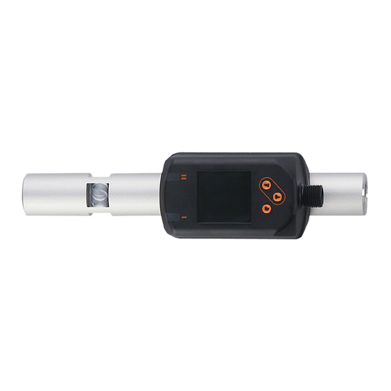
- Page 1 Operating instructions Air gap sensor SDP110...
-
Page 2: Table Of Contents
SDP110 Air gap sensor Contents Preliminary note ............. - Page 3 Air gap sensor SDP110 10.2.5.1 Standard display ..........27 10.2.5.2...
-
Page 4: Preliminary Note
SDP110 Air gap sensor 1 Preliminary note You will find instructions, technical data, approvals and further information using the QR code on the unit / packaging or at www.ifm.com. 1.1 Symbols used Requirement Instructions Reaction, result [...] Designation of keys, buttons or indications... -
Page 5: Safety Instructions
Air gap sensor SDP110 2 Safety instructions • The unit described is a subcomponent for integration into a system. – The system architect is responsible for the safety of the system. – The system architect undertakes to perform a risk assessment and to create documentation in accordance with legal and normative requirements to be provided to the operator and user of the system. -
Page 6: Intended Use
SDP110 Air gap sensor 3 Intended use The unit monitors the distance value with the help of compressed air in industrial use. The unit detects the process values distance, flow velocity, volume flow (flow rate/time) and pressure. 3.1 Application area All indications apply to standard volume flow to DIN ISO 2533, i.e. volume flow at 1013 mbar (101.3 kPa), 15 °C and 0 % relative air humidity. -
Page 7: Function
Air gap sensor SDP110 4 Function • The unit detects the distance of a workpiece using flow measurement. • The unit detects flow based on the calorimetric measuring principle. • As an additional process value the unit also detects the pressure. -
Page 8: Switching Output
SDP110 Air gap sensor A minimum operating pressure of ≥ 500 mbar (50 kPa) is required for a successful distance measurement. workpiece surface to be monitored Ø measuring nozzle sensor Fig. 1: Example: surface to be monitored with 2 measuring nozzles The distance between workpiece and surface to be monitored must not exceed a maximum distance depends on the diameter of the measuring nozzles and must not exceed the measuring range of the unit. -
Page 9: Analogue Output
Air gap sensor SDP110 When the hysteresis function is set, the set point [SP] and the reset point [rP] are defined. The rP value must be lower than the SP value. The distance between SP and rP is at least 4 % of the final value of the measuring range (= hysteresis). -
Page 10: Measured Value Damping
SDP110 Air gap sensor [mA] FOU=On 21,5 20,5 FOU=OFF [bar] [µm] 1000 [none] Fig. 4: Characteristics of the analogue output according to the standard IEC 60947-5-7 Analogue signal MAW: Initial value of the measuring range (with setting of low flow cut-off for Q: signal output starting at MAW + LFC) Process value (Q;... -
Page 11: Simulation
IO-Link is an internationally standardised IO technology (IEC 61131-9) for communicating with sensors and actuators. General information about IO-Link can be found at io-link.ifm. IO Device Description (IODD) with all parameters and process data of the unit can be found at documentation.ifm.com. - Page 12 SDP110 Air gap sensor • Freely definable parameters to identify the units in the plant. • Additional parameter and diagnostic functions (events) compared to the SIO mode. • Data storage: Automatic transfer of parameters when a unit is replaced. •...
-
Page 13: Mounting
Air gap sensor SDP110 5 Mounting CAUTION If the medium temperature is above 50 °C (122 °F), parts of the housing can increase in temperature to over 65 °C (149 °F). w Risk of burns. u Protect the housing against contact with flammable substances and unintentional contact. -
Page 14: Installation Location
SDP110 Air gap sensor 5.2 Installation location u For the continuous elimination of condensation water and particles in the compressed air system, make sure the unit is installed in a position higher than the measuring nozzles. Fig. 7: Installation location 5.3 Process connection u Fit the unit in the pipe in accordance with the flow direction (arrow on the unit): Tighten both adapters in opposite direction by applying the defined tightening torque of 50 Nm:... -
Page 15: Measuring Nozzle Geometry
Air gap sensor SDP110 5.6 Measuring nozzle geometry In order to achieve an optimal measuring performance of the unit, the measuring nozzles should have the following characteristics: • The measuring nozzle is 1.5 times longer than its diameter at the outlet. -
Page 16: Electrical Connection
SDP110 Air gap sensor 6 Electrical connection The device must be connected by a qualified electrician. Observe the national and international regulations for the installation of electrical equipment. Voltage supply according to EN 50178, SELV, PELV. u Disconnect power. u Connect the unit as follows:... -
Page 17: Operating And Display Elements
Air gap sensor SDP110 7 Operating and display elements Switching status LED for OUT1 Switching status LED for OUT2 TFT display Keys for changing views and parameter setting Fig. 11: Operating and display elements Display illumination: Unit temperature > 70 °C: brightness automatically reduced. -
Page 18: Menu
SDP110 Air gap sensor 8 Menu The figures in which the menus are displayed show the parameters that can be set on the unit by key input. These parameters and other functions are also available via the IO-Link interface. 8.1 Menu overview Use the operating keys to navigate from the process value display to the main menu and from there to the submenus. - Page 19 Air gap sensor SDP110 Process value display t.SP1 t.SP2 ASP2 AEP2 rES, Info, OUT1, OUT2, CFG, MEM, DIS, COLR, SIM Fig. 13: Main menu Main menu - - - - - - - - Info OUT1 OUT1 OUT2 OUT2 COLR COLR...
- Page 20 SDP110 Air gap sensor SEL1 DIST FLOW PRES Hno Hnc Fno Fnc OFF OUT1 FOU1 OU On OFF Fig. 15: Output 1 [OUT1] menu SEL2 DIST FLOW PRES Hno Hnc Fno Fnc tch ASP2 AEP2 OUT2 FOU2 OU On OFF Fig. 16: Output 2 [OUT2] menu uni.F...
- Page 21 Air gap sensor SDP110 Lo.D Hi.D Lo.F Hi.F Lo.P Hi.P Fig. 18: Min/max memory [MEM] menu diS.L L2.Flow L2.Pres diS.U d1 d2 d3 diS.R 0 90 180 270 diS.B 25 50 75 100 OFF Fig. 19: Display settings [DIS] menu coL.D bk/wh red green yellow r-cF G-cF - - - cFH.D...
-
Page 22: Set-Up
SDP110 Air gap sensor 9 Set-up After power-on and expiry of the power-on delay time of approx. 1 s, the unit is in the normal operating mode. It carries out its measurement and evaluation functions and generates output signals according to the set parameters. -
Page 23: Parameter Setting
For parameter setting via the IO-Link interface, you need suitable parameter setting software and the IO Device Description (IODD) for the unit. • IODD, parameter setting software and information on IO-Link at io-link.ifm. Notes on parameter setting Ò Manual of the parameter setting software. •... -
Page 24: Function Tag
SDP110 Air gap sensor 10.1.2.2 Function Tag • Customer-specific functional description. • Maximum length 32 characters and freely definable. 10.1.2.3 Location Tag • Customer-specific application description. • Maximum length 32 characters and freely definable. 10.1.3 Parameters The unit is configured via the parameters. The parameters described below are only available via the IO-Link interface. -
Page 25: Process Value For Outx
Air gap sensor SDP110 10.2.2.1 Process value for OUTx u Select the OUTx menu. u Select [SELx] and set the process value for output x: • DIST: Distance • FLOW: Flow • PRES: Pressure 10.2.2.2 Standard unit of measurement u Select the CFG menu. -
Page 26: Distance Teach
SDP110 Air gap sensor 10.2.4 Distance teach With distance teach, a switching point SP is set for the current object distance. The reset point rP is changed with a fixed set value (80 % SP). The window function is not available for the distance teach. -
Page 27: User Settings (Optional)
SDP110 u Use the system commands [SP1 teach] or [SP2 teach] to set the parameters for limit values of the unit. More detailed information can be found in the IODD at www.ifm.com. 10.2.5 User settings (optional) 10.2.5.1 Standard display u Select the DIS menu. -
Page 28: Output Logic
SDP110 Air gap sensor 10.2.5.4 Output logic u Select the CFG menu. u Select [P-n] and set PnP or nPn. 10.2.5.5 Measured value damping u Select the CFG menu. u Select [dAP.F] for flow measurement or [dAP.P] for pressure measurement and set damping constant in seconds ( τ... -
Page 29: Factory Reset
Air gap sensor SDP110 Locking: u Make sure that the unit is in the normal operating mode. u Press [▲] and [▼] simultaneously for 10 s until [Set menu lock] is displayed. Unlocking: u Make sure that the unit is in the normal operating mode. - Page 30 SDP110 Air gap sensor • On: The simulation starts. The values are simulated for the time set under S.Tim. Abort by pressing any key. • OFF: The simulation is not active.
-
Page 31: Operation
Air gap sensor SDP110 11 Operation 11.1 Process value display It is possible to switch between different process value indications during operation: u Press [▲] or [▼]. w The display changes between the standard indication with set standard unit of measurement and other views. -
Page 32: Troubleshooting
SDP110 Air gap sensor 12 Troubleshooting The unit has many self-diagnostic options. It monitors itself automatically during operation. Warnings and error states are displayed even if the display is switched off. Error indications are also available via IO-Link. The status signals are classified according to NAMUR recommendation NE107. - Page 33 Air gap sensor SDP110 Display Problem/remedy • Title line: --- Parameter setting via keys locked, parameter setting is active via IO-Link communication. • Process value line: Lock via communication u Finish parameter setting via IO-Link communication. • Title line: --- Setting keys locked via parameter setting software, parameter change rejected.
-
Page 34: Maintenance, Repair And Disposal
SDP110 Air gap sensor 13 Maintenance, repair and disposal 13.1 Maintenance The unit is maintenance-free. 13.2 Repair Only the manufacturer is allowed to repair the unit. u Flush the unit at regular intervals with higher pressure (maximum 16 bar) to remove any soiling in the measuring channel. -
Page 35: Factory Setting
Air gap sensor SDP110 14 Factory setting Menu Parameters Factory setting User setting OUT1 SEL1 DIST SP1 / FH1 100 µm rP1 / FL1 98 µm FOU1 OUT2 SEL2 DIST ASP2 0 µm AEP2 250 µm FOU2 uni.F uni.D µm uni.P dAP.F...
Need help?
Do you have a question about the SDP110 and is the answer not in the manual?
Questions and answers