Table of Contents
Advertisement
Quick Links
Advertisement
Table of Contents

Related Manuals for IFM SI0553


Summary of Contents for IFM SI0553
- Page 1 Operating instructions Flow monitor SI0553 SI5011 SI5012 SI5100...
-
Page 2: Table Of Contents
SI0553 SI5011 SI5012 SI5100 Flow monitor Contents Preliminary note ............. -
Page 3: Preliminary Note
Flow monitor SI0553 SI5011 SI5012 SI5100 1 Preliminary note You will find instructions, technical data, approvals and further information using the QR code on the unit / packaging or at documentation.ifm.com. 1.1 Symbols used Requirement Instructions Reaction, result [...] Designation of keys, buttons or indications... -
Page 4: Intended Use
SI0553 SI5011 SI5012 SI5100 Flow monitor • Only use the product for its intended purpose (Ò Intended use). • Only use the product for permissible media. • If the operating instructions or the technical data are not adhered to, personal injury and/or damage to property may occur. -
Page 5: Installation
Flow monitor SI0553 SI5011 SI5012 SI5100 5 Installation CAUTION During installation or in case of mechanical failure, high pressure or hot media can leak from the system. w Risk of injury caused by pressure or burns. u Ensure that the system is free of pressure during installation. -
Page 6: Impermissible Installation Position
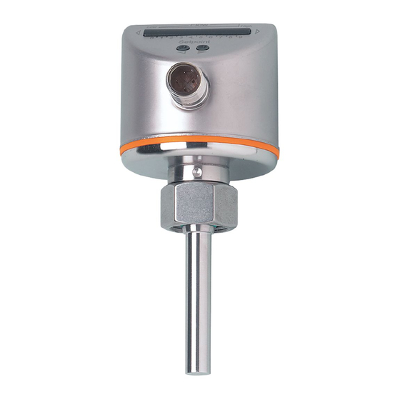
5.3 Process connection Using process adapters the unit can be adapted to different process connections. A correct fit of the unit and ingress resistance of the connection are only ensured using ifm adapters. For small flow rates, ifm adapter blocks are available. -
Page 7: Electrical Connection
Flow monitor SI0553 SI5011 SI5012 SI5100 u Place the flow monitor onto the adapter and tighten the nut. Tightening torque 25 Nm. Ensure that the unit is correctly oriented. 6 Electrical connection The unit must be connected by a qualified electrician. -
Page 8: Set-Up
SI0553 SI5011 SI5012 SI5100 Flow monitor 8 Set-up u Switch on the supply voltage. w All LEDs light and go out again step by step. During this time, the output is closed if set to normally open and open if set to normally closed. -
Page 9: Low-Flow Adjustment
Flow monitor SI0553 SI5011 SI5012 SI5100 u Let the normal flow circulate in the installation. u Press [►] and keep it pressed. w LED 9 is on, after approx. 5 seconds it flashes. u Release [►]. w The device is adapted to the flow conditions. It goes into operating mode. -
Page 10: Lock / Unlock
SI0553 SI5011 SI5012 SI5100 Flow monitor • Output function: normally open • Not locked 9.6 Lock / unlock The unit can be locked electronically to prevent unauthorised setting. Factory setting: not locked. u Press both setting keys for 10 seconds. w The display goes off. -
Page 11: Operation
Flow monitor SI0553 SI5011 SI5012 SI5100 10 Operation The device detects the flow and switches the output according to the setting. The device displays the current flow and the switching status. In case of power failure or interruption of the operating voltage, all settings remain. - Page 12 SI0553 SI5011 SI5012 SI5100 Flow monitor u Ensure that the sensor tip is free from build-up: • Check the sensor tip for build-up one month after set-up. • Repeat check regularly. Determine check intervals based on the application. • In case of soiling clean the sensor tip with a soft cloth. Stubborn build-up, such as lime, can be removed using a common vinegar cleaning agent.
Need help?
Do you have a question about the SI0553 and is the answer not in the manual?
Questions and answers