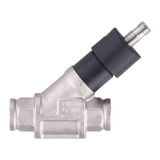
IFM SB 4 Series Operating Instructions Manual
Mechatronic flow sensor
Hide thumbs
Also See for SB 4 Series:
- Operating instructions manual (31 pages) ,
- Operating instructions manual (33 pages)
Table of Contents
Advertisement
Quick Links
Advertisement
Table of Contents

Summary of Contents for IFM SB 4 Series
- Page 1 Operating instructions Mechatronic flow sensor SBx4xx...
-
Page 2: Table Of Contents
SBx4xx Mechatronic flow sensor Contents Preliminary note ............. . Symbols used. -
Page 3: Preliminary Note
Mechatronic flow sensor SBx4xx 1 Preliminary note You will find instructions, technical data, approvals and further information using the QR code on the unit / packaging or at www.ifm.com. 1.1 Symbols used Requirement Instructions Reaction, result [...] Designation of keys, buttons or indications... -
Page 4: Safety Instructions
SBx4xx Mechatronic flow sensor 2 Safety instructions • The unit described is a subcomponent for integration into a system. – The system architect is responsible for the safety of the system. – The system architect undertakes to perform a risk assessment and to create documentation in accordance with legal and normative requirements to be provided to the operator and user of the system. -
Page 5: Intended Use
Mechatronic flow sensor SBx4xx 3 Intended use The unit monitors liquid media (water, glycol solutions, industrial oils, coolants). It detects the volume flow (flow rate/time) and outputs an analogue signal that is proportional to the process value. ATTENTION Frost formation of the medium. w The sensor may be damaged. -
Page 6: Function
SBx4xx Mechatronic flow sensor 4 Function The unit detects the flow according to the principle of differential pressure by means of a permanent magnet and a measuring cell. 4.1 Analogue output The analogue signal for water is linear from 4 mA (= no flow) to 20 mA I [mA] (= final value of the measuring range, VMR). -
Page 7: Mounting
Mechatronic flow sensor SBx4xx 5 Mounting CAUTION During installation or in case of a fault (e.g. housing damage) media under high pressure or hot media can leak from the system. w Risk of injury caused by pressure or burns. u Ensure that the system is free of pressure during installation. u Ensure that no media can leak at the mounting location during installation. -
Page 8: Mounting Accessories
Fig. 3: Installation with mounting plate Threaded hole M8 (depth 6 mm) on the bottom side of the unit Information about available accessories at www.ifm.com 5.4 Installation in case of water containing dirt u Use a 200-micron filter in front of the inlet (IN). -
Page 9: Electrical Connection
Voltage supply according to EN 50178, SELV, PELV. u Disconnect power. u Connect the unit as follows: 1 BN 2 WH 3 BU Fig. 5: Wiring diagram (colours in accordance with DIN EN60947-5-2) Brown White Blue Information about available sockets / plugs at www.ifm.com. -
Page 10: Troubleshooting
SBx4xx Mechatronic flow sensor 7 Troubleshooting If there are dirt particles between the float and the housing the display value of the sensor does not return to zero in case of flow standstill. In case of contamination the display value can be up to 30 % of the final value of the measuring range. -
Page 11: Maintenance, Repair And Disposal
Mechatronic flow sensor SBx4xx 8 Maintenance, repair and disposal The operation of the unit is maintenance-free. Only the manufacturer is allowed to repair the unit. u After use dispose of the device in an environmentally friendly way in accordance with the applicable national regulations.


Need help?
Do you have a question about the SB 4 Series and is the answer not in the manual?
Questions and answers