Table of Contents
Advertisement
Quick Links
Advertisement
Table of Contents

Subscribe to Our Youtube Channel
Related Manuals for IFM SBU3 Series


Summary of Contents for IFM SBU3 Series
- Page 1 Operating instructions Mechatronic flow sensor SBU3xx...
-
Page 2: Table Of Contents
SBU3xx Mechatronic flow sensor Contents Preliminary note ............. Symbols used . -
Page 3: Preliminary Note
Mechatronic flow sensor SBU3xx 1 Preliminary note You will find instructions, technical data, approvals and further information using the QR code on the unit / packaging or at www.ifm.com. 1.1 Symbols used Requirement Instructions Reaction, result [...] Designation of keys, buttons or indications... -
Page 4: Safety Instructions
SBU3xx Mechatronic flow sensor 2 Safety instructions • The unit described is a subcomponent for integration into a system. – The system architect is responsible for the safety of the system. – The system architect undertakes to perform a risk assessment and to create documentation in accordance with legal and normative requirements to be provided to the operator and user of the system. -
Page 5: Intended Use
Mechatronic flow sensor SBU3xx 3 Intended use The unit detects liquid media (glycol solutions, industrial oils, coolants). It detects the volume flow (flow rate/time) according to the principle of differential pressure and switches the output. The switch point is adjustable. ATTENTION Frost formation of the medium. -
Page 6: Mounting
SBU3xx Mechatronic flow sensor 4 Mounting CAUTION During installation or in case of a fault (e.g. housing damage) media under high pressure or hot media can leak from the system. w Risk of injury caused by pressure or burns. u Ensure that the system is free of pressure during installation. u Ensure that no media can leak at the mounting location during installation. -
Page 7: Electrical Connection
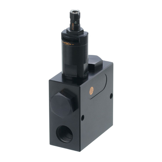
Voltage supply according to EN 50178, SELV, PELV. u Disconnect power. u Connect the unit as follows: 4 BK 3 BU Fig. 2: Wiring diagram (colours in accordance with DIN EN60947-5-2) Brown Black Blue Information about available sockets / plugs at www.ifm.com. -
Page 8: Settings
SBU3xx Mechatronic flow sensor 6 Settings There are 2 options to set the switch point: • Set the switch point on the unit. • Carry out the flow adjustment. L/min L/min Fig. 3: Switch point setting Yellow LED (switching status) Setting scale Lock nut Knurl Do not turn the knurl beyond the maximum value of the setting range (Ò... -
Page 9: Operation
Mechatronic flow sensor SBU3xx 7 Operation After power on, the unit is ready for operation. The unit detects the volumetric flow quantity and switches the output according to the setting. • Output closed (LED = ON), if volumetric flow quantity ≥ switch point. •... -
Page 10: Maintenance, Repair And Disposal
SBU3xx Mechatronic flow sensor 8 Maintenance, repair and disposal The operation of the unit is maintenance-free. Only the manufacturer is allowed to repair the unit. u After use dispose of the device in an environmentally friendly way in accordance with the applicable national regulations.
Need help?
Do you have a question about the SBU3 Series and is the answer not in the manual?
Questions and answers