
Related Manuals for IFM SB1 Series


Summary of Contents for IFM SB1 Series
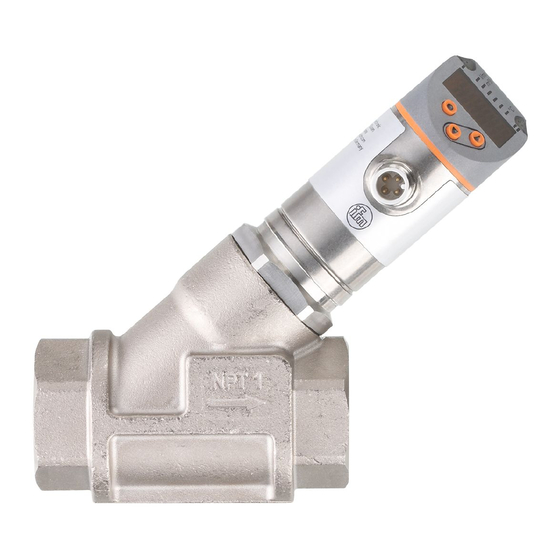
- Page 1 Operating instructions Mechatronic flow sensor SB1xxx SB2xxx SB3xxx SB4xxx SB5xxx SB6xxx SB7xxx SB8xxx SB9xxx SB03xx...
-
Page 2: Table Of Contents
Contents Preliminary note ���������������������������������������������������������������������������������������������������4 1�1 Symbols used ������������������������������������������������������������������������������������������������4 2 Safety instructions �����������������������������������������������������������������������������������������������4 3 Functions and features ����������������������������������������������������������������������������������������5 4 Function ���������������������������������������������������������������������������������������������������������������5 4�1 Switching function ������������������������������������������������������������������������������������������6 4�2 Analogue function ������������������������������������������������������������������������������������������6 4�2�1 Volumetric flow monitoring ��������������������������������������������������������������������7 4�2�2 Temperature monitoring ������������������������������������������������������������������������8 4�3 Frequency output �������������������������������������������������������������������������������������������8 4�4 Customer-specific calibration (CGA) �������������������������������������������������������������9 4�5 IO-Link ���������������������������������������������������������������������������������������������������������10 4�6 Measured value damping ����������������������������������������������������������������������������10... - Page 3 9�2�3 Limit value monitoring with OUT2 / hysteresis function ����������������������23 9�2�4 Limit value monitoring with OUT2 / window function ��������������������������23 9�2�5 Configure the analogue output for volumetric flow �����������������������������24 9�2�6 Configure the frequency signal for volumetric flow �����������������������������24 9�3 Settings for temperature monitoring ������������������������������������������������������������24 9�3�1 Limit value monitoring with OUT1 / hysteresis function ����������������������24 9�3�2 Limit value monitoring with OUT1 / window function ��������������������������24 9�3�3 Limit value monitoring with OUT2 / hysteresis function ����������������������25...
-
Page 4: Preliminary Note
1 Preliminary note Technical data, approvals, accessories and further information at www�ifm�com� 1.1 Symbols used ► Instructions > Reaction, result […] Designation of keys, buttons or indications → Cross-reference Important note Non-compliance may result in malfunction or interference� Information Supplementary note�... -
Page 5: Functions And Features
• Installation, electrical connection, set-up, operation and maintenance of the unit must be carried out by qualified personnel authorised by the machine operator� • Protect units and cables against damage� 3 Functions and features The unit monitors industrial oils� It detects the two process categories volumetric flow and medium temperature� 4 Function •... -
Page 6: 4�1 Switching Function
4.1 Switching function OUTx changes its switching status if it is above or below the set switching limits (flow or temperature)� Hysteresis or window function can be selected� Example of volumetric flow monitoring: Hysteresis function Window function SP = set point FH = upper limit value rP = reset point FL = lower limit value... -
Page 7: 4�2�1 Volumetric Flow Monitoring
4.2.1 Volumetric flow monitoring [mA] FOU=On 21,5 FOU=OFF [% MEW] Figure 1 Analogue signal Volumetric flow quantity Measuring range Display range Detection zone MAW: Initial value of the measuring range MEW: Final value of the measuring range Above the display range Err: The unit is in the error state�... -
Page 8: 4�2�2 Temperature Monitoring
4.2.2 Temperature monitoring [mA] FOU=On 21,5 FOU=OFF [°C] [°F] Figure 2 Analogue signal Medium temperature Measuring range Display range Detection zone MAW: Initial value of the measuring range MEW: Final value of the measuring range Above the display range Below the display range Err: The unit is in the error state�... -
Page 9: 4�4 Customer-Specific Calibration (Cga)
Up to the limit value set under [FEP1] (for OUT1 = TEMP: between the limit values set under [FSP1] and [FEP1]) the frequency signal is between 0 Hz and the frequency value set under [FrP ]� 130 % 120 % FrP1 = 100 % FSP1... -
Page 10: 4�5 Io-Link
IO-Link hardware and software visit www�ifm�com� 4.6 Measured value damping With measured value damping, a delay time can be set by means of which the unit provides an erratically occurring flow change�... -
Page 11: 4�7 Colour Change Display (Colr)
The damping time is added to the response time of the sensor (→ Technical data). The signals [UL] and [OL] (→ 12) are defined under consideration of the damping time� 4.7 Colour change display (coLr) The colour of the characters in the display can be set via the parameter [coLr] (→... -
Page 12: Installation
5 Installation CAUTION During installation or in case of a fault (housing damage) media under high pressure or hot media can leak from the system� > Risk of burns� ► Ensure that the system is free of pressure during installation� ►... -
Page 13: 5�1 Installation In Case Of Oil Containing Dirt
The sensor head can be rotated by 360°� ► The following minimum distances must be adhered to: Distance between the sensor head and ferromagnetic materials� ≥ 30 mm * Distance between the sensor head and constant / alternating fields� ≥ 500 mm Distance between the sensor axes for side-by-side installation�... - Page 14 OUT2 BK: black OUT1 BN: brown BU: blue WH: white Colours to DIN EN 60947-5-2 • Switching signal: limit values for volumetric flow quantity • Switching signal: limit values for temperature 4 (OUT1) • Frequency signal for volumetric flow quantity •...
-
Page 15: Operating And Display Elements
7 Operating and display elements 1, 2, 3: Indicator LEDs 1: switching status OUT1 (lights if output 1 is switched) 2: process value in the indicated unit of measurement: l/min; m /h; gpm; gph; °C; °F 3: switching status OUT2 (lights if output 2 is switched) 4: Alphanumeric display, 4 digits •... -
Page 16: Menu
8 Menu 8.1 Main menu Process value display (RUN) FSP1 FEP1 FEP1 FrP1 FrP1 EF _ CFG, MEM, DIS Parameters are indicated in case of factory setting → 14� Parameters are only displayed when selected at [ou1] und [ou2] → 8.2�... - Page 17 Explanation main menu Switching output with hysteresis function Set point 1 = upper limit value at which OUT1 switches Reset point 1 = lower limit value at which OUT1 is reset Set point 2 = upper limit value at which OUT2 switches Reset point 2 = lower limit value at which OUT2 is reset Switching output with window function Upper limit value at which OUT1 switches...
-
Page 18: 8�2 Extended Functions - Basic Settings (Cfg)
8.2 Extended functions – Basic settings (CFG) Main menu Hno Hnc Fno Fnc FRQ - - - - Hno Hnc Fno Fnc CFG _ uni.F Lmin MEM _ uni.T °C °F DIS _ FOU1 FOU2 SEL1 FLOW TEMP SEL2 FLOW TEMP Explanation extended functions (EF) Restoring the factory settings... - Page 19 Explanation basic settings (CFG) ou1 / ou2 Output functions OUT1 / OUT2 (flow and temperature) Hno = Hysteresis function normally open Hnc = Hysteresis function normally closed Fno = Window function normally open Fnc = Window function normally closed FRQ = Frequency output = Analogue signal 4���20 mA�...
-
Page 20: 8�3 Min/Max Memory (Mem) - Display (Dis)
8.3 Min/max memory (MEM) – Display (DIS) Main menu Lo.T 1234 CFG _ Hi.T 1234 MEM _ coLr GrEn DIS _ r1ou G1ou r2ou G2ou rd3 OFF SELd FLOW TEMP Explanation min/max memory (MEM) Lo�T Min� value of the temperature measured in the process Hi�T Max�... -
Page 21: Parameter Setting
Update rate and orientation of the display d1 = update of the measured values every 50 ms� d2 = update of the measured values every 200 ms� d3 = update of the measured values every 600 ms� rd1, rd2, rd3 = display as for d1, d2, d3; rotated by 180°� OFF = the measured value display is deactivated in the Run mode�... -
Page 22: 9�1�1 Select Submenu
9.1.1 Select submenu ► Click [▲] or [▼] to select submenu (EF, CFG, MEM, DIS). ► Briefly press [●] to change to the submenu. 9.1.2 Exit parameter setting or menu level ► Press [▲] + [▼] simultaneously� > Return to the next higher menu level� The changed parameter settings are not accepted�... -
Page 23: 9�2 Settings For Consumed Quantity Monitoring
9.2 Settings for consumed quantity monitoring 9.2.1 Limit value monitoring with OUT1 / hysteresis function ► Select [SEL1] and set [FLOW]� Menu CFG: ► Select [ou1] and set the switching function: [SEL1] - [Hno] = hysteresis function/normally open [ou1] - [Hnc] = hysteresis function/normally closed Main menu: ►... -
Page 24: 9�2�5 Configure The Analogue Output For Volumetric Flow
9.2.5 Configure the analogue output for volumetric flow ► Select [SEL2] and set [FLOW]� Menu CFG: ► Select [ou2] and set the function: [SEL2] - [I] = current signal proportional to volumetric flow (4…20 mA) [ou2] 9.2.6 Configure the frequency signal for volumetric flow ►... -
Page 25: 9�3�3 Limit Value Monitoring With Out2 / Hysteresis Function
9.3.3 Limit value monitoring with OUT2 / hysteresis function ► Select [SEL2] and set [TEMP]� Menu CFG: ► Select [ou2] and set the switching function: [SEL2] - [Hno] = hysteresis function/normally open [ou2] - [Hnc] = hysteresis function/normally closed Main menu: ►... -
Page 26: 9�4 User Settings (Optional)
9.4 User settings (optional) 9.4.1 Set the standard unit of measurement for volumetric flow ► Select [uni�F] and set the unit of measurement: l/min, m /h, gpm, gph� Menu CFG: [uni�F] 9.4.2 Set the standard unit of measurement for temperature ►... -
Page 27: 9�4�7 Set Output Status In Fault Condition
9.4.7 Set output status in fault condition ► Select [FOU1] and set the value: Menu CFG: 1� Switching output: [FOU1] - [On] = output 1 switches ON in case of an error� [FOU2] - [OFF] = output 1 switches OFF in case of an error� - [OU] = output 1 switches irrespective of the fault as defined with the parameters�... -
Page 28: 9�5�2 Resetting All Parameters To Factory Setting
9.5.2 Resetting all parameters to factory setting ► Select [rES]� Menu EF: ► Press [●]. [rES] ► Press [▲] or [▼] and keep pressed until [----] is displayed. ► Briefly press [●]. It is recommended to take down your own settings in the table before carrying out the function →... -
Page 29: Technical Data
11 Technical data Technical data and scale drawing at www�ifm�com� 12 Troubleshooting 12.1 Measurement error caused by dirt If there are dirt particles between the float and the housing the display value of the sensor does not return to zero in case of flow standstill� In case of dirt the display value can be up to 30 % of the final value of the measuring range�... -
Page 30: Maintenance, Repair And Disposal
13 Maintenance, repair and disposal If used correctly, no maintenance and repair measures are necessary� Only the manufacturer is allowed to repair the unit� After use dispose of the unit in an environmentally friendly way in accordance with the applicable national regulations� In case of heavily polluted media: ►... -
Page 32: Factory Setting
14 Factory setting Parameter Factory setting User setting SP1 / FH1 (FLOW) 20 % rP1 / FL1 (FLOW) 19 % SP1 / FH1 (TEMP) 70°C rP1 / FL1 (TEMP) 20 °C FrP1 (FLOW/TEMP) 10 % FSP1 (TEMP) -10 °C FEP1 (TEMP) 100 °C FEP1... - Page 33 The percentage values refer to the final value of the measuring range (MEW)� Technical data, approvals, accessories and further information at www�ifm�com�...
Need help?
Do you have a question about the SB1 Series and is the answer not in the manual?
Questions and answers