
Related Manuals for MR MESSKO EI100


Summary of Contents for MR MESSKO EI100
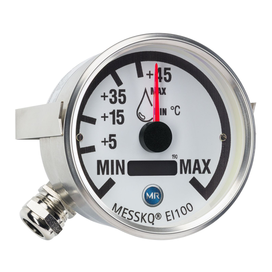
- Page 1 MESSKO EI100, EI100/160 ® ELEKTRONISCHE FERNANZEIGE ELEKTRONIC INDICATOR Betriebsanleitung / Operating Instructions BA2 053 /09/05 D E- EN ME SS K O INS TRUMENT S...
- Page 2 BA2053/09/05...
-
Page 3: Table Of Contents
Messko Inhaltsverzeichnis/Contents Inhaltsverzeichnis/Contents Inhaltsverzeichnis Contents Sicherheit........4 Safety ........4 Sicherheitshinweise . -
Page 4: Sicherheit
1 Sicherheit/Safety Sicherheit Safety Sicherheitshinweise Safety instructions Alle Personen, die mit der Montage, Inbetriebnahme, All personnel involved in installation, commissioning, Bedienung, Wartung und Instandhaltung des Geräts zu tun operation or maintenance of this equipment must: haben, müssen - be suitably qualified and - fachlich ausreichend qualifiziert sein und - strictly observe these operating instructions. -
Page 5: Produktbeschreibung
2 Produktbeschreibung/Product specification Bei der elektrischen Installation sind die nationalen Vor- Electrical installation is subject to the relevant national schriften zu beachten. Um einen störungsfreien Betrieb zu safety regulations. It is imperative to connect the protective gewährleisten, ist der Schutzleiter unbedingt anzuschließen. conductor in order to ensure trouble-free operation. -
Page 6: Montage
4 Elektrische Anschlüsse/Electrical connections Montage Installation ACHTUNG CAUTION Die in dieser Montage- und Betriebsanleitung vorge- The operating and installation conditions demanded by schriebenen Betriebs- und Montagebedingungen müssen this installation and operating manual must be strictly strikt eingehalten werden. complied with. Der EI100 bzw. - Page 7 4 Elektrische Anschlüsse/Electrical connections Bild 6/Fig. 6 Bild 5/Fig. 5 Elektrischer Anschluss EI100/160/Electrical connection Elektrischer Anschluss EI100/Electrical connection EI100 EI100/160 Beispiele für passive Sensoren: Examples of passive sensors: A) Öltemperatur A) Oil temperature Thermometer MT-ST 160 SK/TT oder Kombi-Hülse/TT Thermometer MT-ST 160 SK/TT or combi sleeve/TT siehe Stromlaufplan 8.1, Seite 11 See current circuit diagram 8.1, page 11 B) Wicklungstemperatur...
-
Page 8: Funktionsprüfung
6 Technische Daten/Technical data Funktionsprüfung Function test - Überprüfen Sie den elektrischen Anschluss des EI 100 bzw. - Check the electrical connection of the El 100 or EI100/160 EI100/160 anhand der Stromlaufpläne unter Kapitel 8. using the circuit diagram in chapter 8. - Schalten Sie die Versorgungsspannung ein. -
Page 9: Anbauzeichnung
7 Maßzeichnungen/Dimensional drawings Prüfberichte: Testing Reports: Prüfung Norm Test Standard Dauerbelastbarkeit VDE 0435 Teil 303 Sustained load capacity VDE 0435 part 303 Kurzzeitstrom VDE 0435 Teil 303 Short-term current VDE 0435 part 303 Störfestigkeit; Impulse IEC 61000-4-4 Fault stability: impulses IEC 61000-4-4 Störfestigkeit;... -
Page 10: Ei100 Mit Klemmbügel
7 Maßzeichnungen/Dimensional drawings EI100 mit Klemmbügel EI100 with clamp strap Bild 8 EI100 mit Klemmbügel Fig. 8 EI100 with clamp strap EI100/160 EI100/160 Bild 9 EI100/160 Fig. 9 EI100/160 BA2053/09/05... -
Page 11: Stromlaufpläne
8 Stromlaufpläne/Circuit diagrams Stromlaufpläne Circuit diagrams Öltemperatur, passiver Sensor Oil temperature, passive sensor ϑ 24VDC 4-20mA Bild 10/Fig. 10 BA2053/09/05... -
Page 12: 8.2 Wicklungstemperatur, Passiver Sensor
8 Stromlaufpläne/Circuit diagrams 8.2 Wicklungstemperatur, passiver Sensor 8.2 Winding temperature, passive sensor Ω Ω Ω Ω Ω Ω Ω Ω Ω Ω Ω Ω 24VDC 4-20mA Bild 11/Fig. 11 BA2053/09/05... -
Page 13: Öltemperatur, Aktiver Sensor
8 Stromlaufpläne/Circuit diagrams Öltemperatur, aktiver Sensor Oil temperature, active sensor 9 10 19 20 Messko POWER ALARM TRIP ERROR EPT 202 24 25 31 32 33 34 40 41 42 43 24VDC 4-20mA Bild 12/Fig. 12 BA2053/09/05... -
Page 14: Wicklungstemperatur, Aktiver Sensor
8 Stromlaufpläne/Circuit diagrams Wicklungstemperatur, aktiver Sensor Winding temperature, active sensor 9 10 19 20 Messko POWER ALARM TRIP ERROR EPT 202 24 25 31 32 33 34 40 41 42 43 24VDC 4-20mA Bild 13/Fig. 13 BA2053/09/05... -
Page 15: Ölstand, Aktiver Sensor
8 Stromlaufpläne/Circuit diagrams Ölstand, aktiver Sensor Oil level, active sensor Bild 14/Fig. 14 BA2053/09/05... - Page 16 Messko GmbH Gewerbegebiet An den Drei Hasen Messko-Platz 1, 61440 Oberursel, Germany Phone: +49 6171 6398-0 Fax: +49 6171 6398-98 Email: info@messko.com www.messko.com Please note: The data in our publications may differ from the data of the devices delivered. We reserve the right to make changes without notice.
Need help?
Do you have a question about the MESSKO EI100 and is the answer not in the manual?
Questions and answers